
|
603-630-5658
|
|
tinypontoonboats@gmail.com
|

|
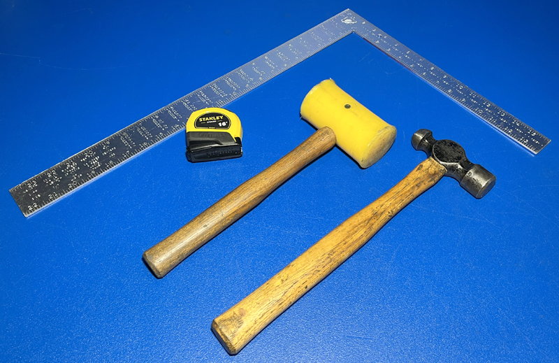
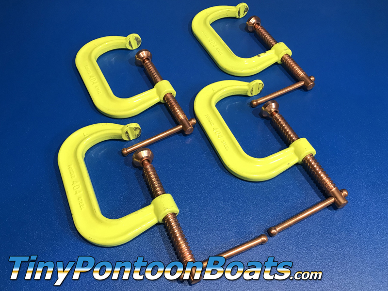
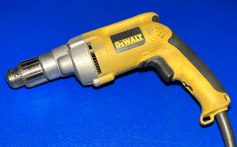
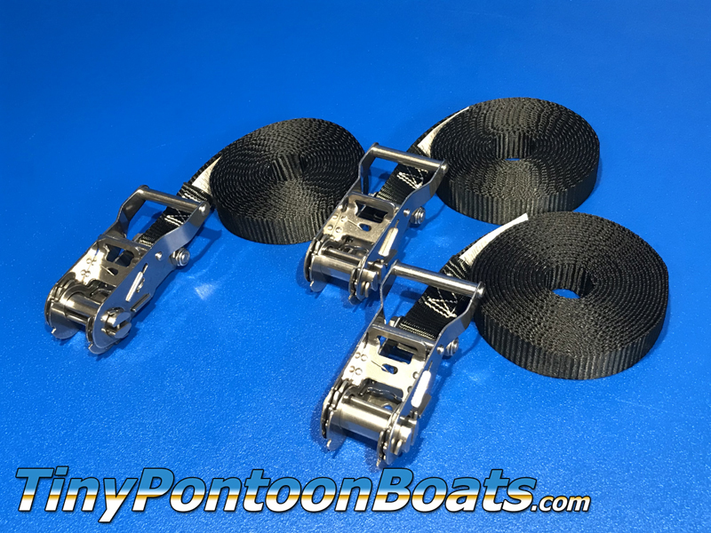
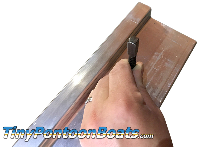
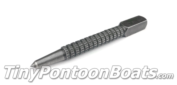
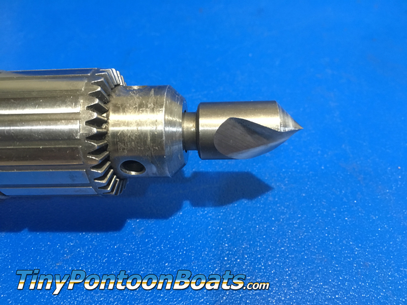
REQUIRED TOOLS
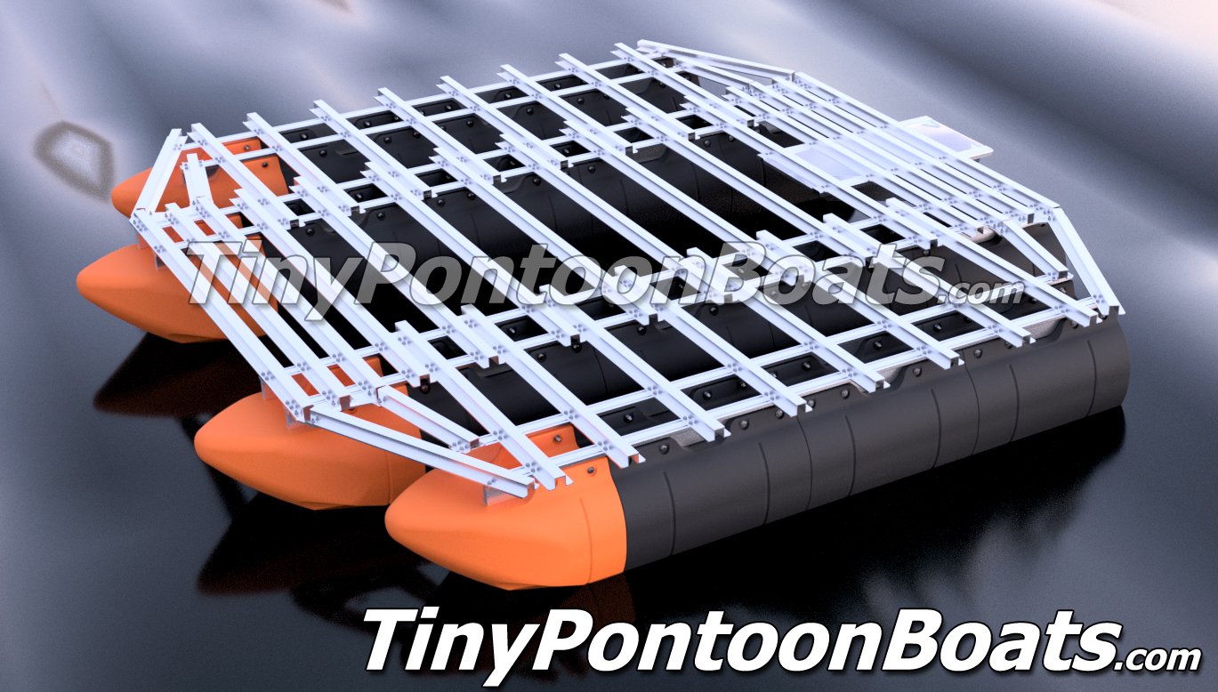
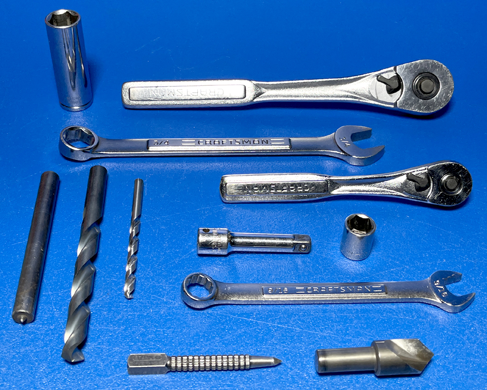
The frame and pontoon assembly for our 15'x15' Flying Octagon tiki style boat kit requires a few basic tools, as well as a couple specialized tools. Below we have provided a list of everything that you'll need, as well as part numbers and links to where you can get the specialized tools from McMaster, which is a reasonably priced industrial supplier. Click on the part number to view the item on the McMaster website. Many customers will already have the majority of these tools, if not all of them. These tools (other than perhaps the transfer punch) should be stocked at your local home supply or hardware store as well.
|
|

|
NOTE
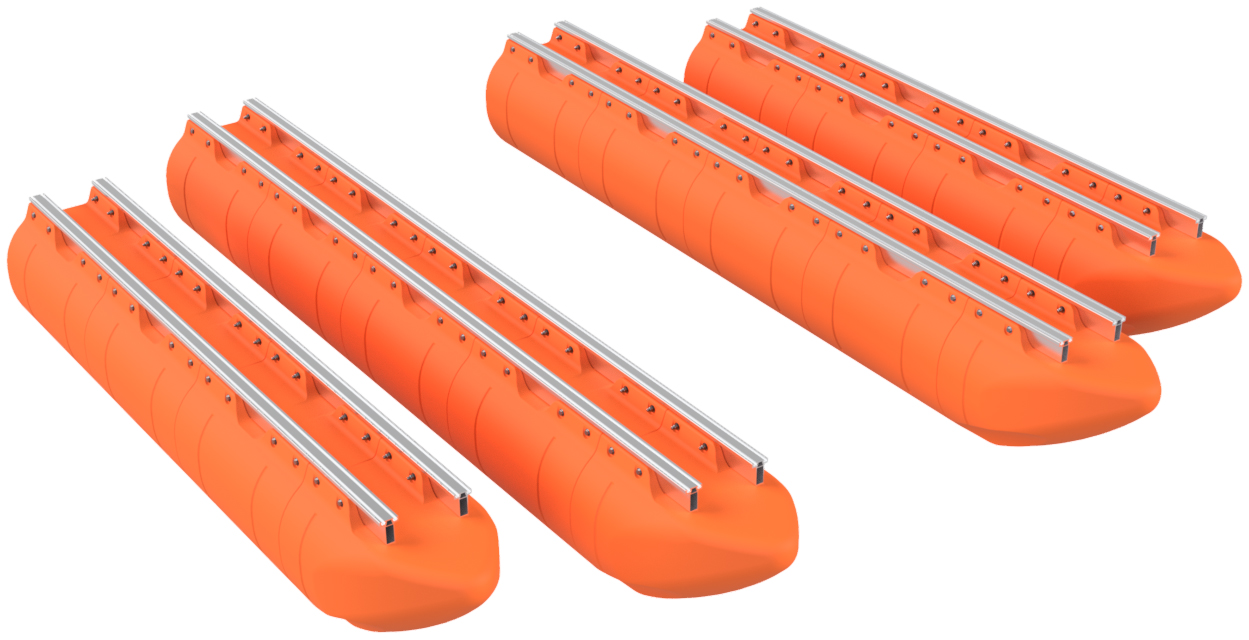
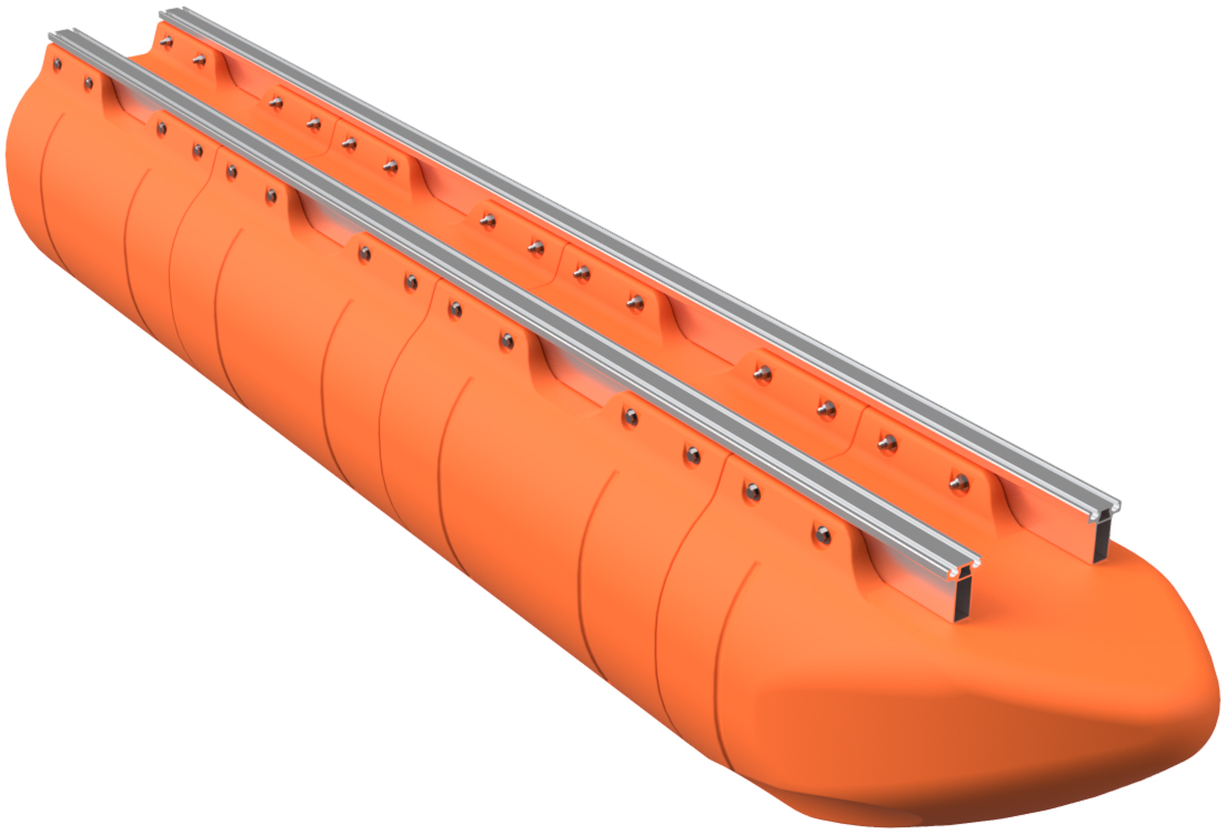
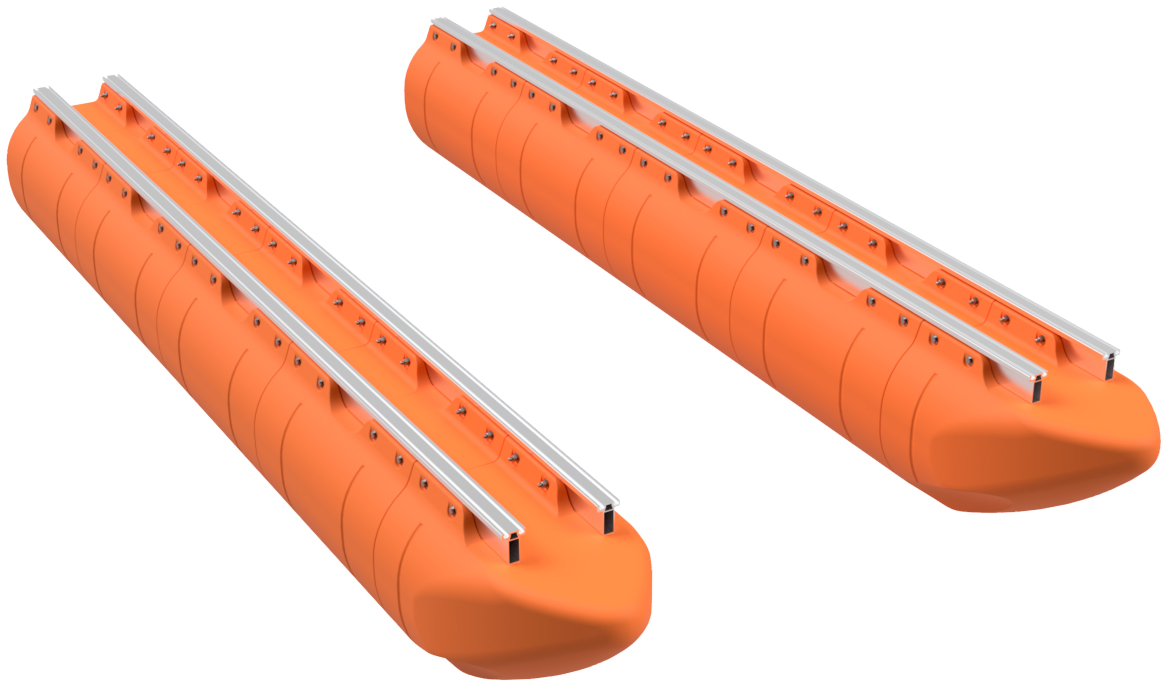
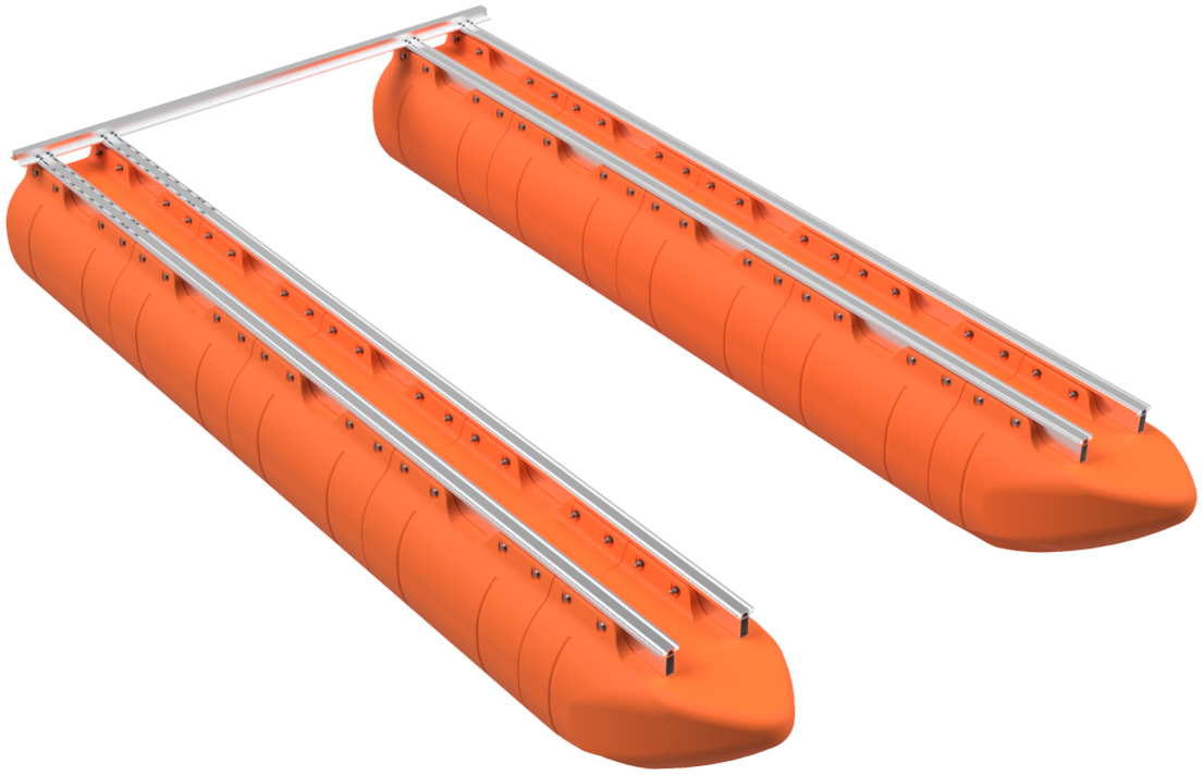
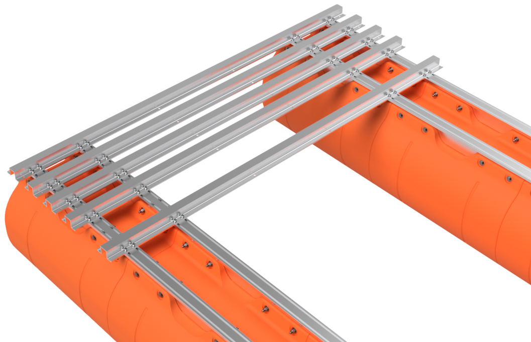
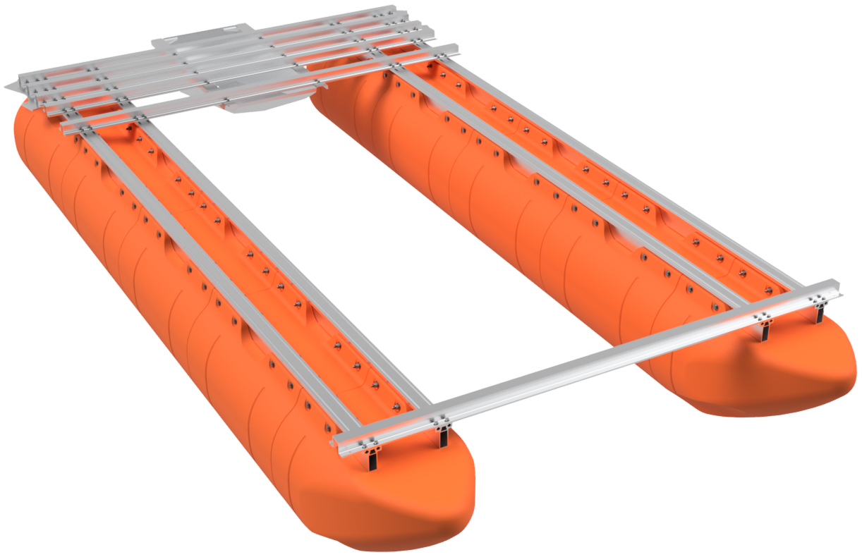
The 15x15 Flying Octagon boat system uses four pontoon assemblies, two that are 15' long and two that are 12' long. All four pontoon assemblies require that you follow the same assembly instructions, being Step 1 through 11 below. We recommend building the 15' long central floats first to get the larger task out of the way.
|
|
|
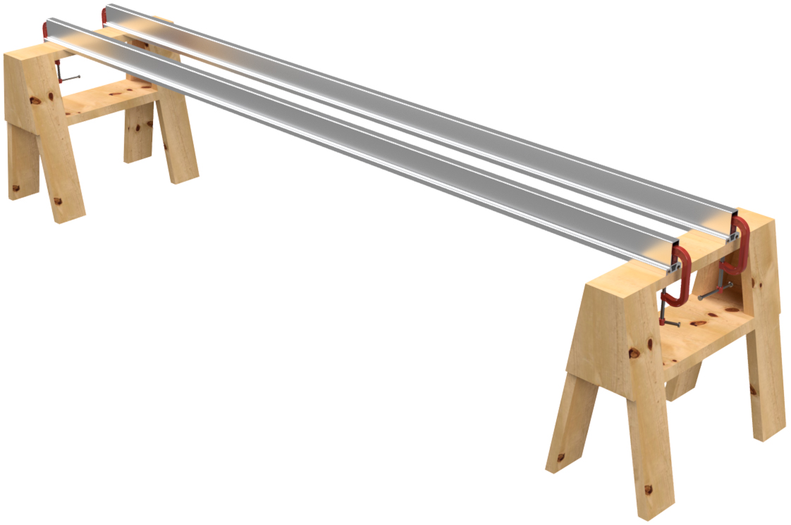
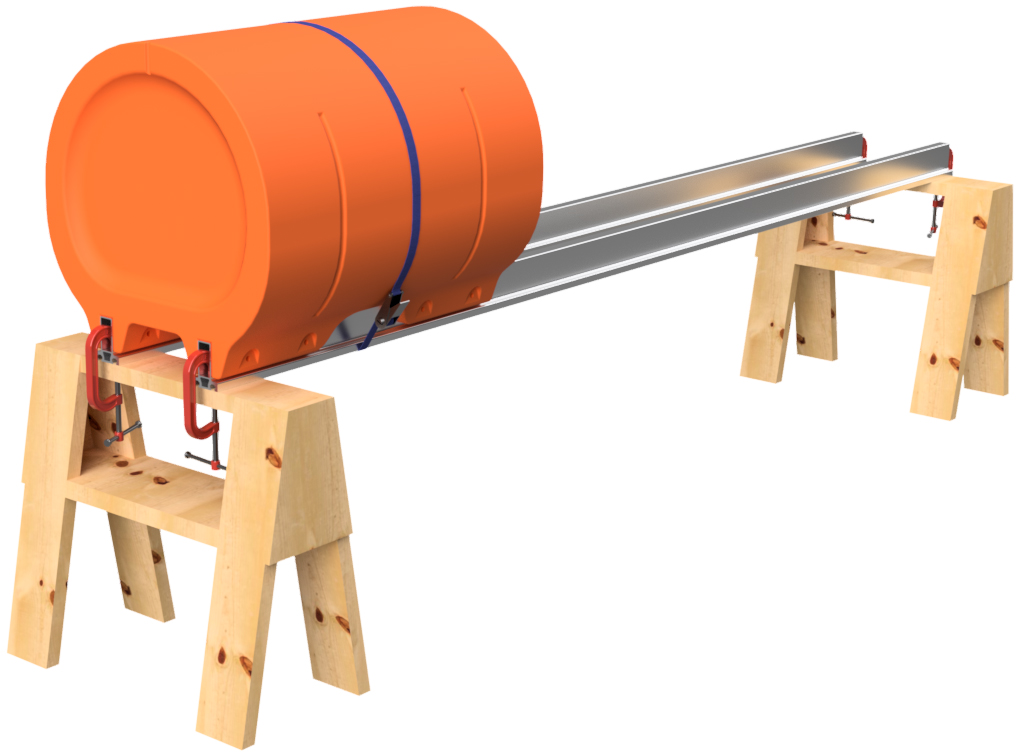
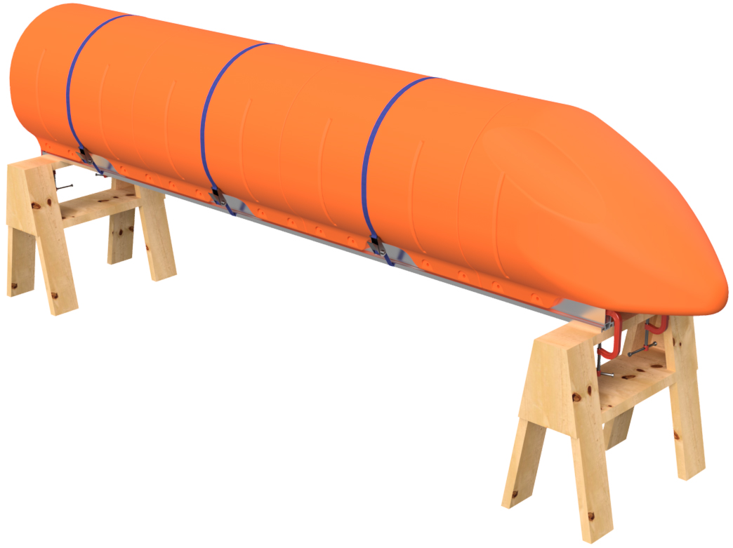
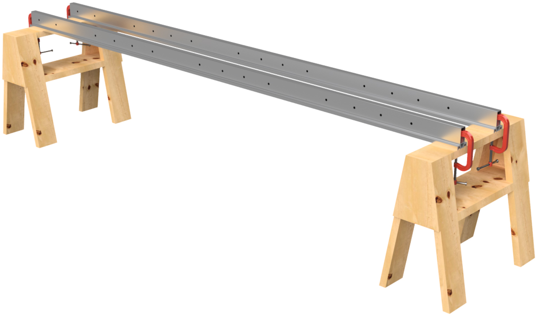
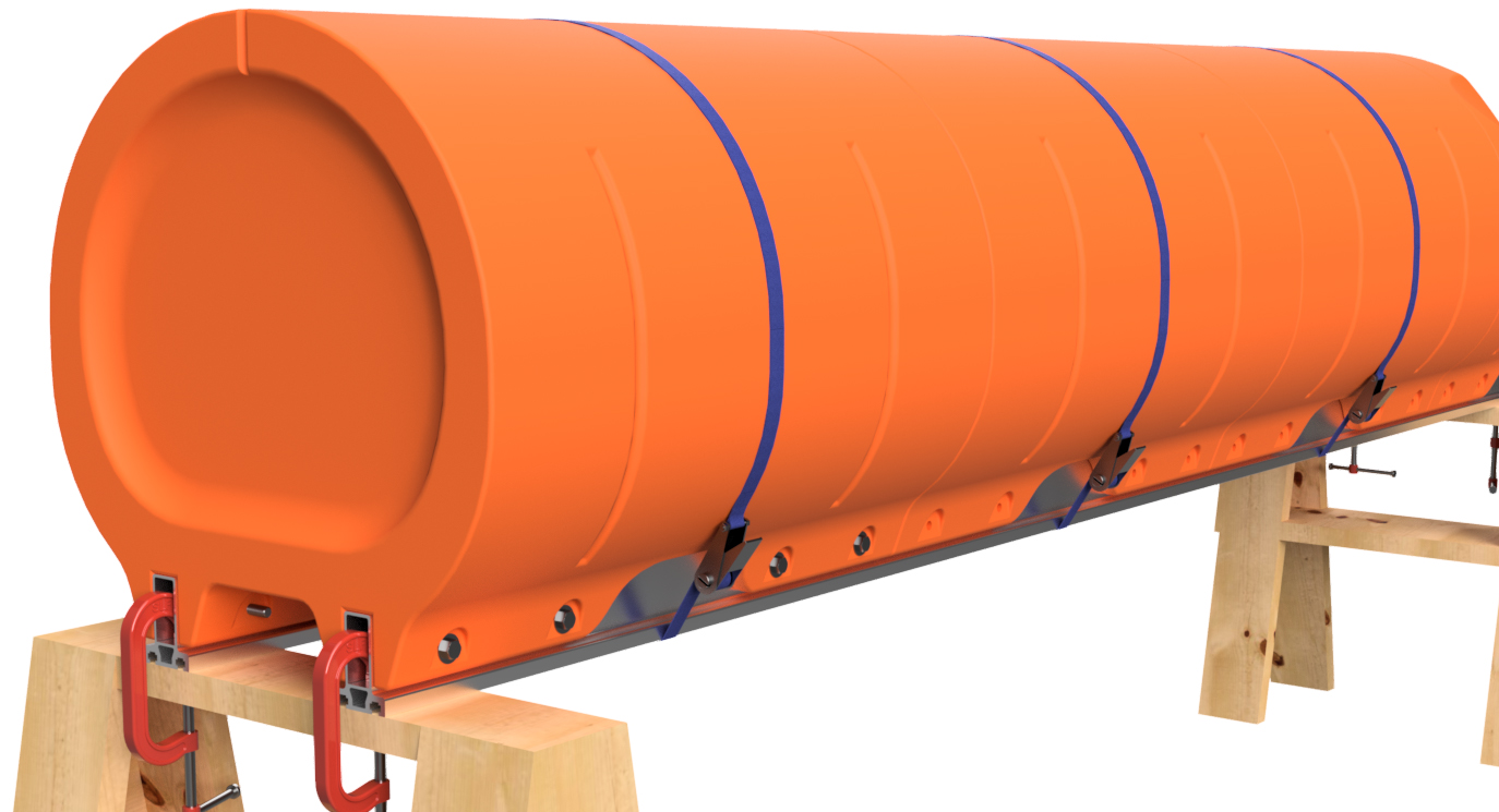
STEP 1
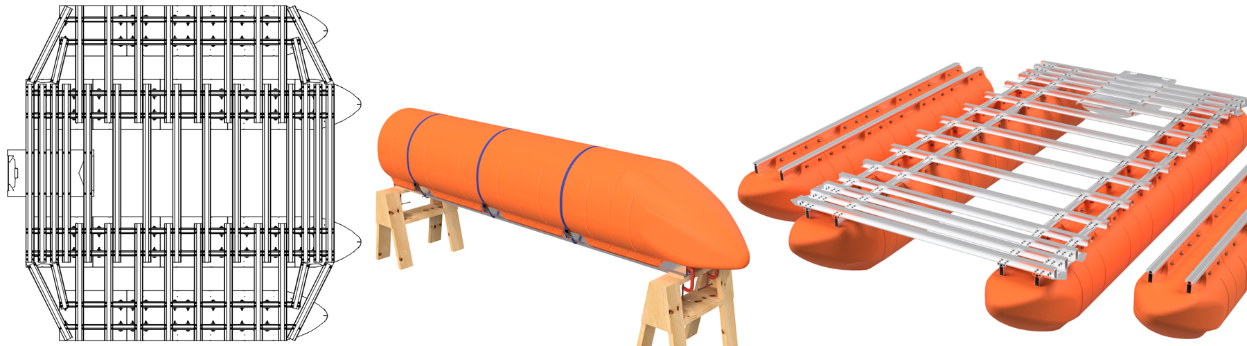
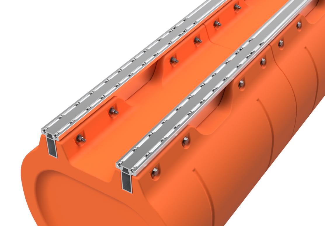
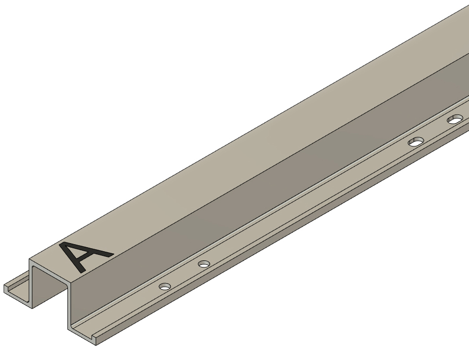
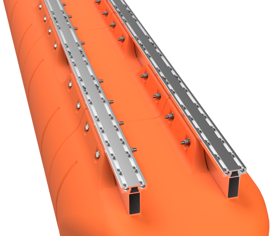
Place two matching length pontoon main beam extrusions across two saw horses. The main beams are the aluminum tubes that have a "T" shaped cross section with two slots on the top. 165" long main beams are for central 15' long pontoon assemblies and 129" long main beams are for the outer 12' long pontoon assemblies. Position the main beams so that the slots face down and are about 12" on center. Use a square to ensure that the ends are even. Clamp the two frame members to your saw horses.
|
|
|
STEP 2
Place one of the straight floats (blunt end floats) on an end of the main beams. You may have to adjust the spacing of your main beams. Tap the float into position so that the end of the float is even with the end of the main beams. A rubber or plastic hammer can be used for this. Place a ratchet strap around the float and the main beams to temporarily hold it in position and ensure that the float is properly seated on the frame members.
|
|
|
STEP 3
Place the remaining straight floats for the pontoon assembly onto the main beams and install ratchet straps around each float. 15' long pontoon assemblies require 4 straight floats per pontoon and 12' pontoon assemblies require 3 straight floats. When placing the floats on the main beams, tap them securely against the previously installed float. Verify that the first float is still even with the end of the main beams and adjust as necessary. Verify that your straps are secured.
|
|
|
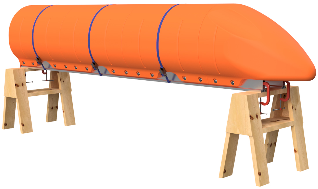
STEP 4
Place a nose cone float on the front of the pontoon assembly as shown. Due to the shape of the nose cone, you will not be able to place a ratchet strap over it.
|
|
|
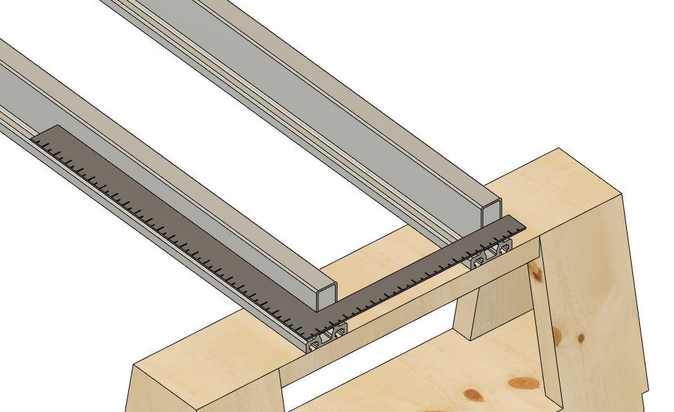
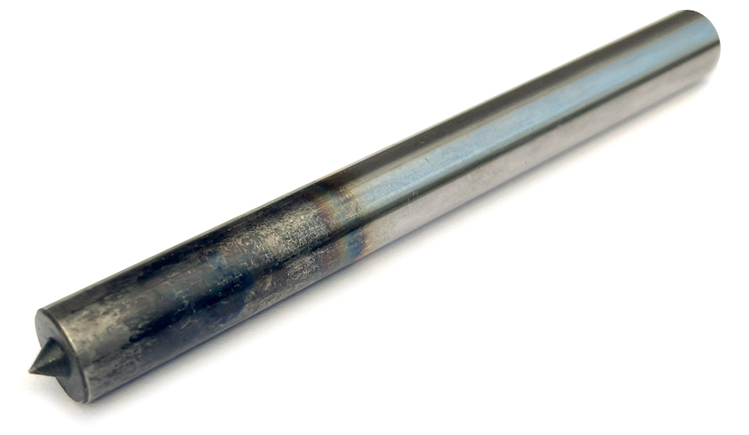
STEP 5
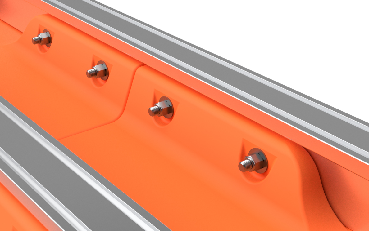
Using a 1/2" transfer punch, go down both sides of both sets of mounting channels on the plastic floats and use the punch with a hammer to mark EVERY bolt hole position through the molded-in bolt holes in the floats. Don't smash it; just give the punch a solid tap. You will have to do this from both the outside set of holes and the inside set of holes. This means that you'll have to go under the pontoon assembly on your saw horses to mark the inner holes. It's inconvenient, but 100% necessary.
|
|
|
STEP 6
Remove the ratchet straps. Before removing the floats, number the positions of the floats on the main beams as shown. Number the floats and main beams on both sides of the pontoon assembly. For instance, if you're building a 12' long pontoon, you'll want to label position 1, 2, 3, and 4 on one side and 5,6,7, and 8 on the other. This ensures that you don't mix up the positions of the floats after you drill holes. You can use a piece of masking tape to write on or you can use a marker to write on the floats and main beams. If using a marker, lacquer paint thinner will remove the ink after assembly, and the paint thinner will not hurt the plastic or the aluminum. Remove the floats and unclamp the main beams from the saw horses.
|
|
STEP 7
Using a standard center punch, make the marks you made with the transfer punch in step 5 more pronounce. This will make the holes easier to drill in the next step.
|
|
|
STEP 8
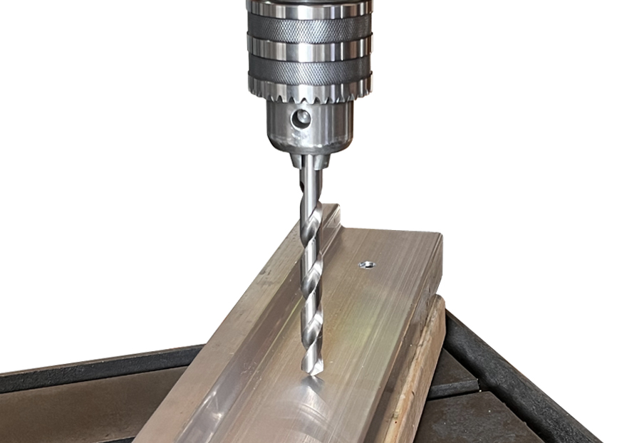
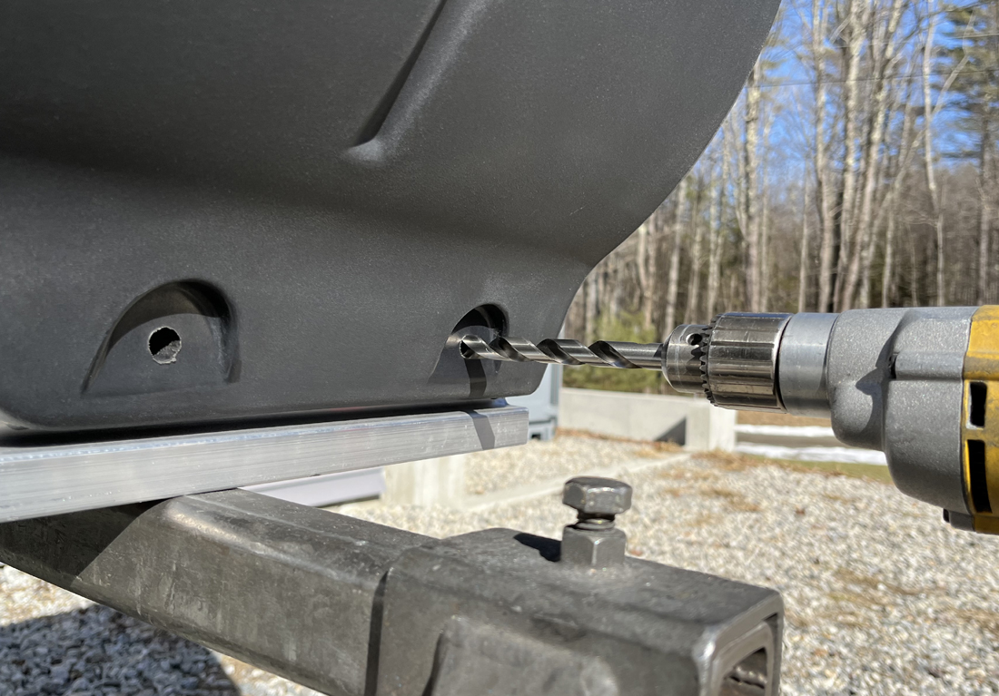
Using a SHARP (prohibits wandering of the bit) 1/4" diameter drill bit, drill through ONE WALL of each main beam at each marked position. DO NOT drill all the way through both sides of the main beams during this operation. Drill through every marked position on one side of each part, flip it, and drill through every marked position on the other side. After drilling all the 1/4" holes in both main beams, use a 1/2" diameter drill bit to drill through every 1/4" hole. Once again, only drill through one wall at a time for each hole position.
For this operation, you can use a hand-held drill, but we find it much easier and quicker to use a drill press. If you have a drill press, you will need to use a spacer block, such as a piece of 2" x 4" lumber, to make the material surface level. If using a hand-held drill, be careful to keep the drill bit perpendicular to the surface you are drilling through. You can't undrill holes, so take your time. After drilling the holes, they must be deburred. We like to use a countersink drill bit for this, but a little bit of sand paper or a file will do the trick as well.
|
|
|
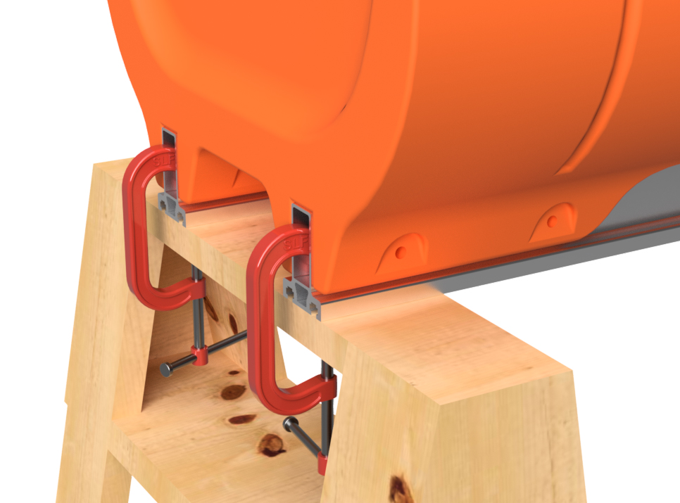
STEP 9
Clamp the main beams back onto the saw horses in the same orientation as before and place the floats back onto the main beams, matching up the numbers you marked in step 6. Place the ratchet straps back over the floats and tap the floats into position so that the holes line up. DO NOT INSERT THE BOLTS YET.
|
|
|
STEP 10
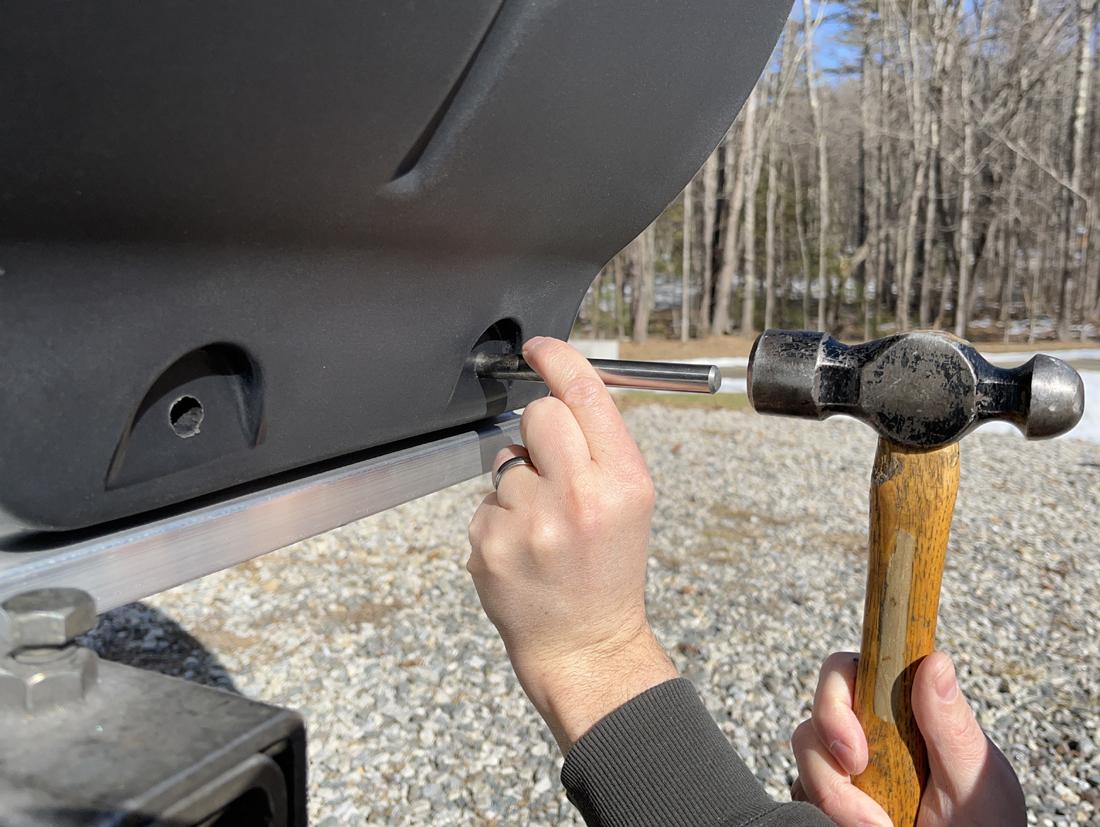
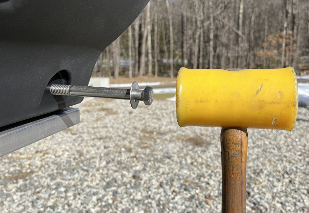
With a 1/2" drill bit mounted in your hand-held drill, start at the back end of the pontoon assembly and drill through one of the the rearmost bolt holes. Drill all the way through both sides of the main beam on that side of the float. You will be drilling inward from the side of the float. When doing this, go slowly, as your drill bit should only be clearing chips and verifying hole alignment, not drilling a new hole.
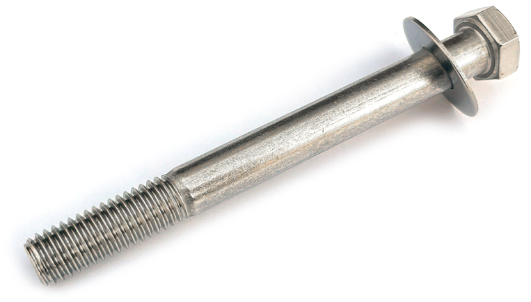
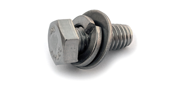
Insert one of the 1/2" x 5" hex bolts with a 1/2" flat washer from the outside position, and tap it through the hole with a hammer. We prefer to use a plastic hammer for this. Drill through the next hole and insert a bolt with washer. Do this on both sides of the pontoon assembly until every float has bolts installed through each hole on both sides of the float. DO NOT INSTALL THE NUTS YET.
|
|
|
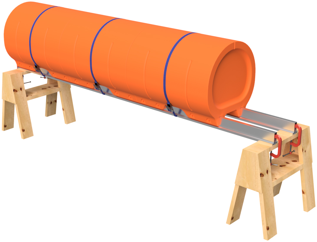
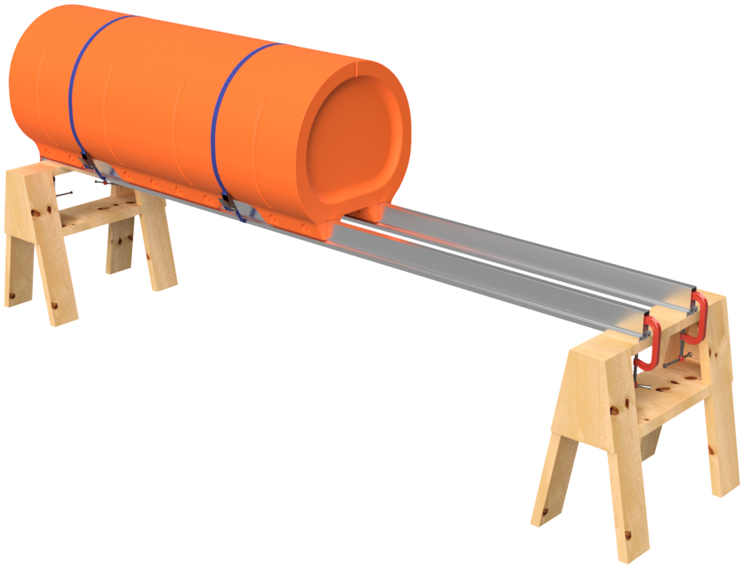
STEP 11
Remove the ratchet straps and flip the pontoon so that it's right side up. As the float will be heavy at this point, please be careful when doing this. When we build boats at Tiny Pontoon Boats, this is when we remove the pontoon assembly from the saw horses and place it on a couple pieces of scrap carpeting on our shop floor. We find it much easier to complete this step with the pontoon on the floor.
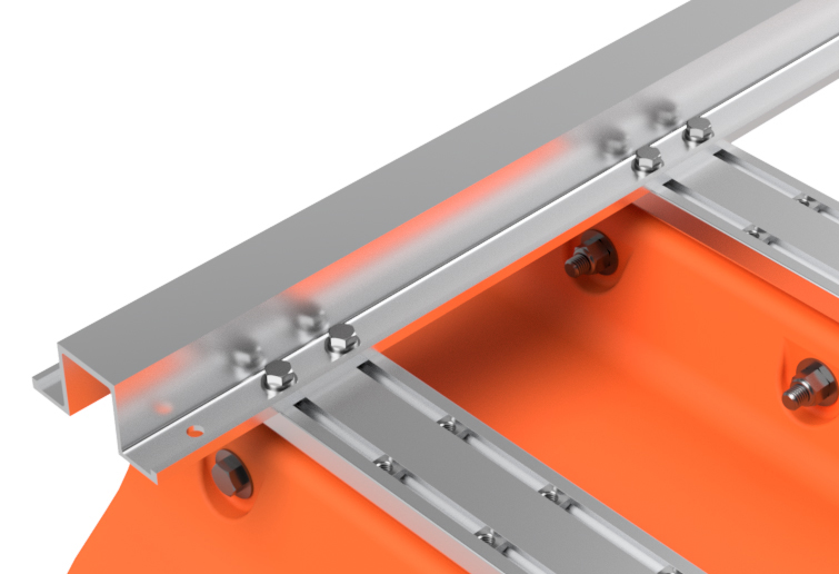
Using a rag, remove any chips from the exposed threads of the bolts you just inserted through the floats. Place 1/2" flat washers over each of the bolts. DO NOT INSTALL THE NUTS YET. Using the included Loctite (blue medium strength Loctite type 242), apply a little bit of the thread locker fluid to each of the bolts. Your kit includes 2 large bottles of Loctite, so more than enough is included. The Loctite lubricates the threads, makes the nuts more secure, and is 100% required. DO NOT SKIP THIS STEP. Thread 1/2" lock nuts onto each of the bolts and tighten the nuts until the mounting flanges on the floats start to flex inward. We do not have a torque specification beyond this. 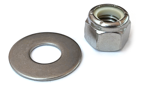 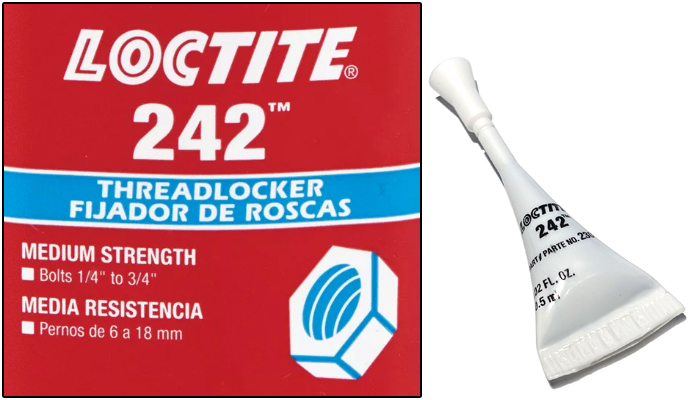
|
|
|
STEP 12
Place the completed pontoon aside and repeat steps 1 through 11 to build your second, third, and fourth pontoon assemblies. After all four are complete, set the 12' outer pontoon assemblies aside and place the 15' pontoon assemblies approximately 74" apart on center.
|
|
|
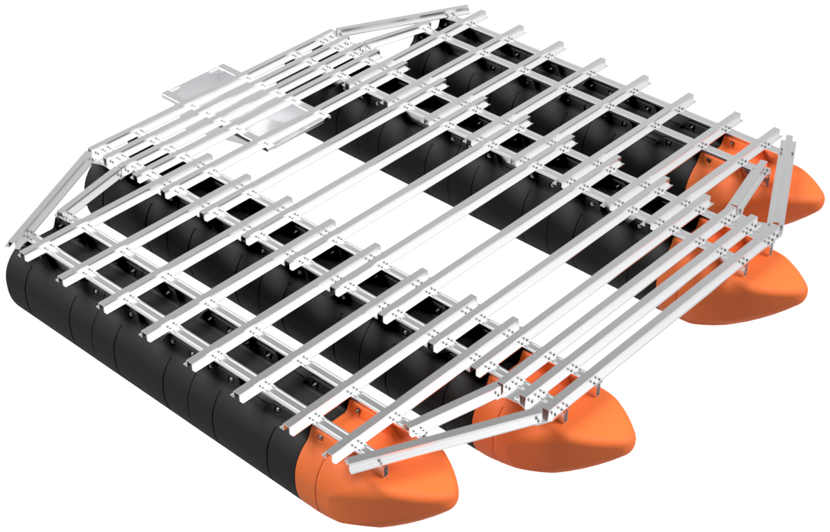
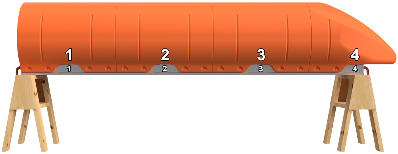
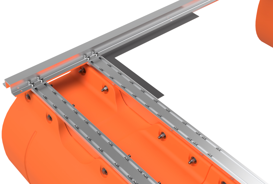
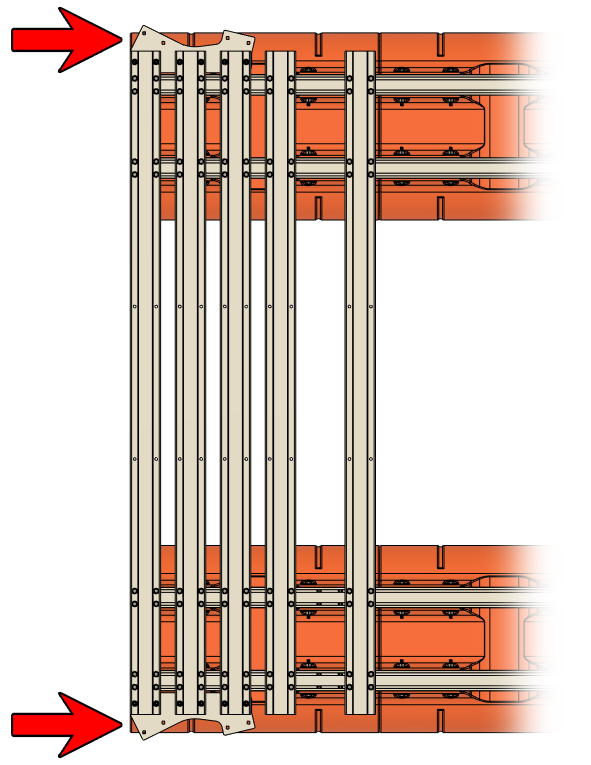
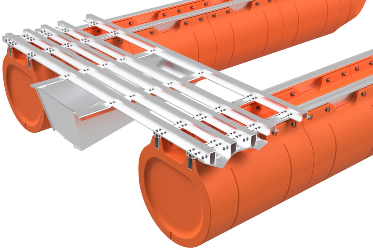
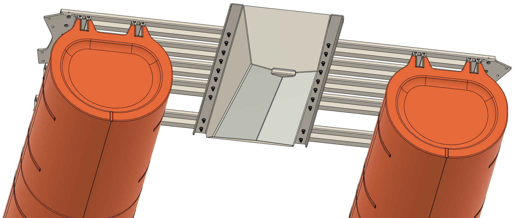
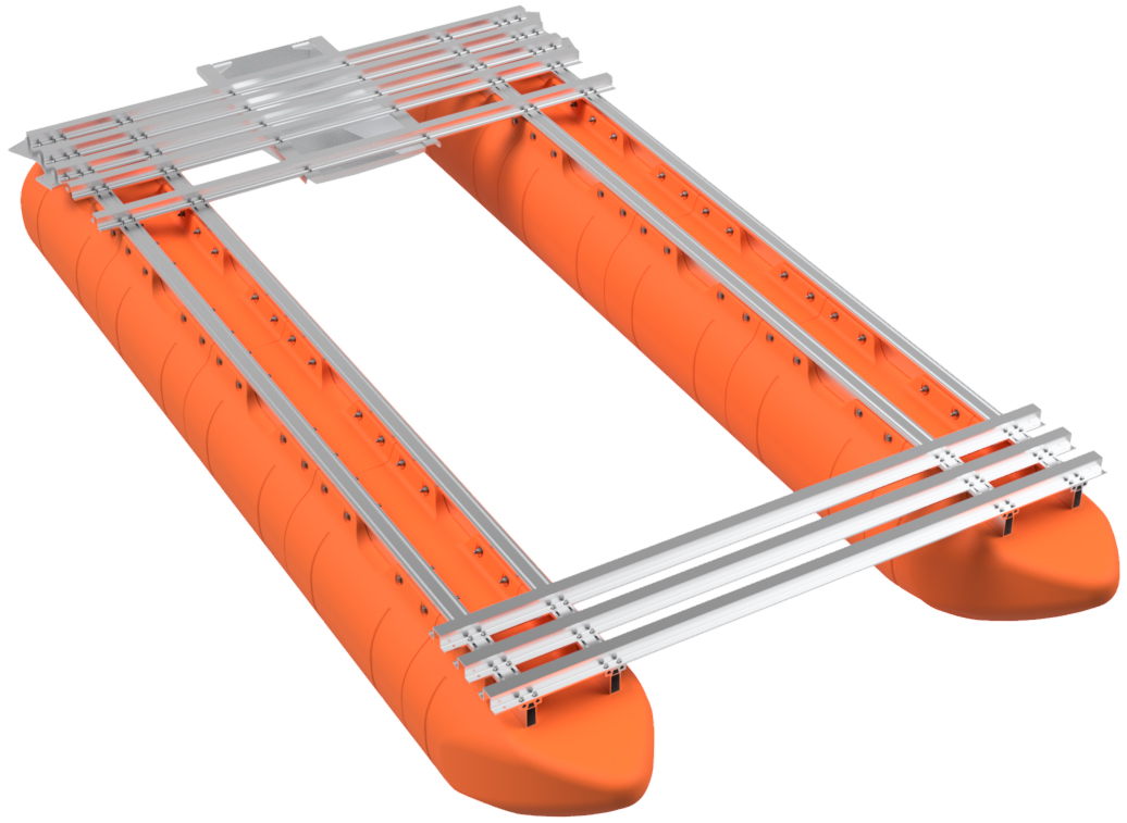
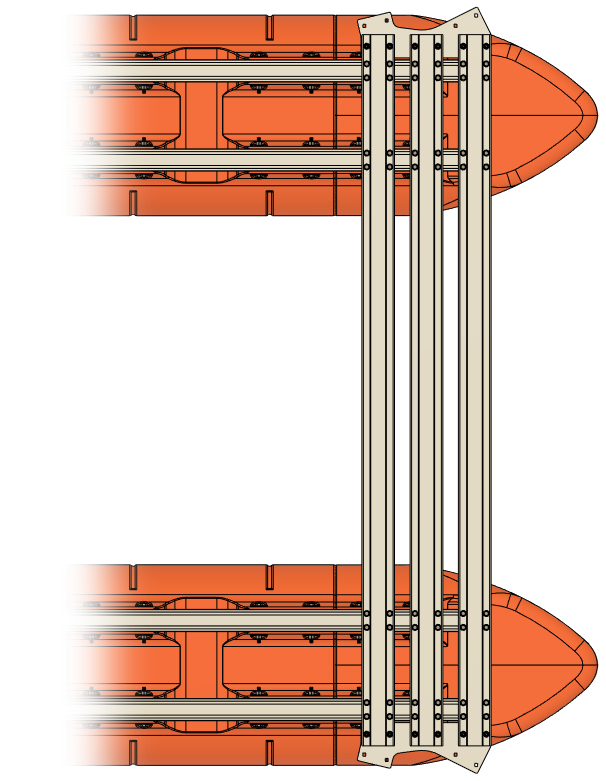
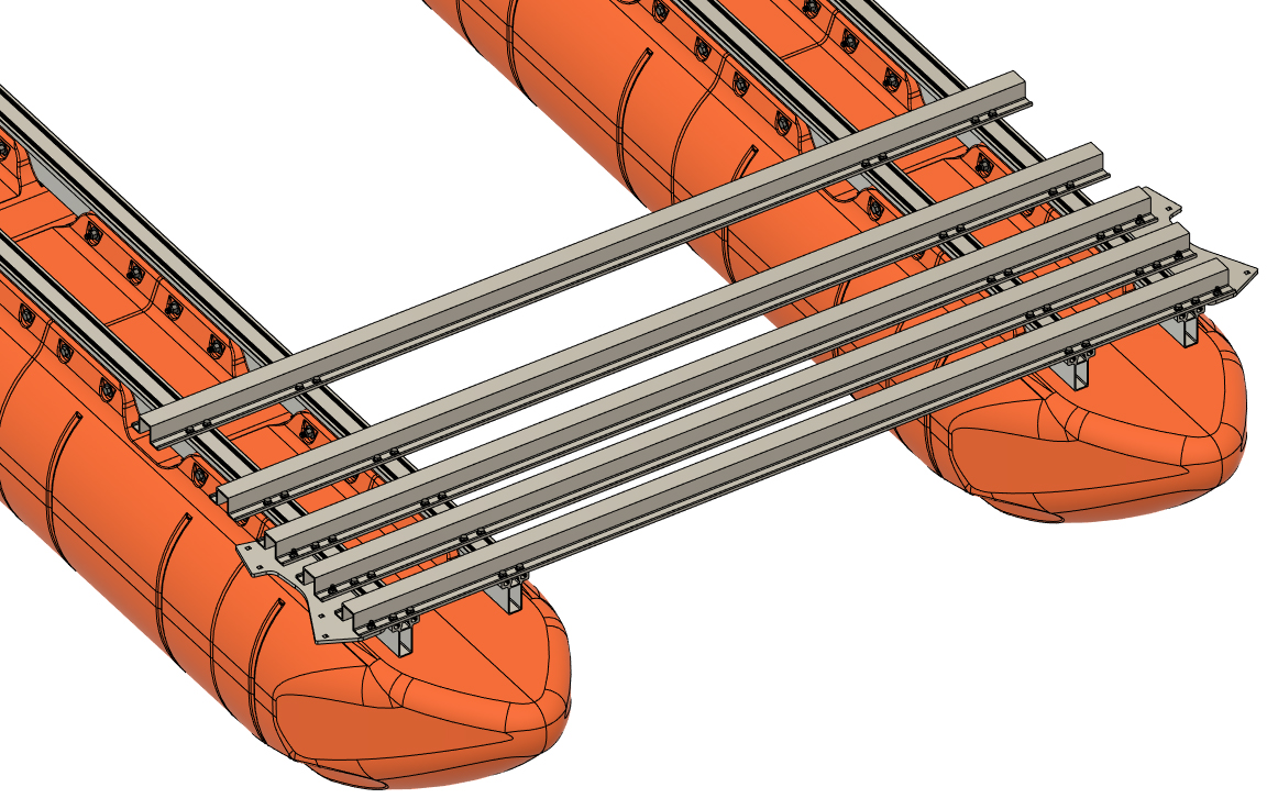
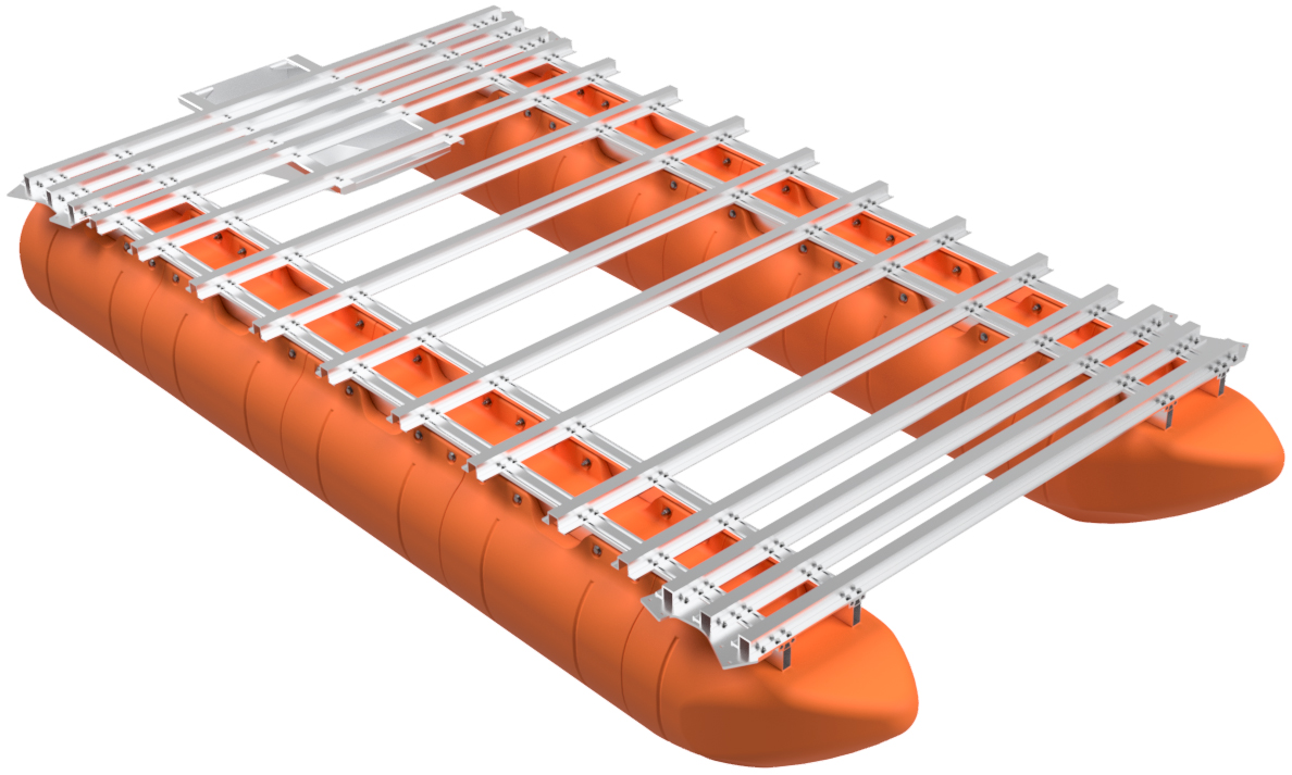
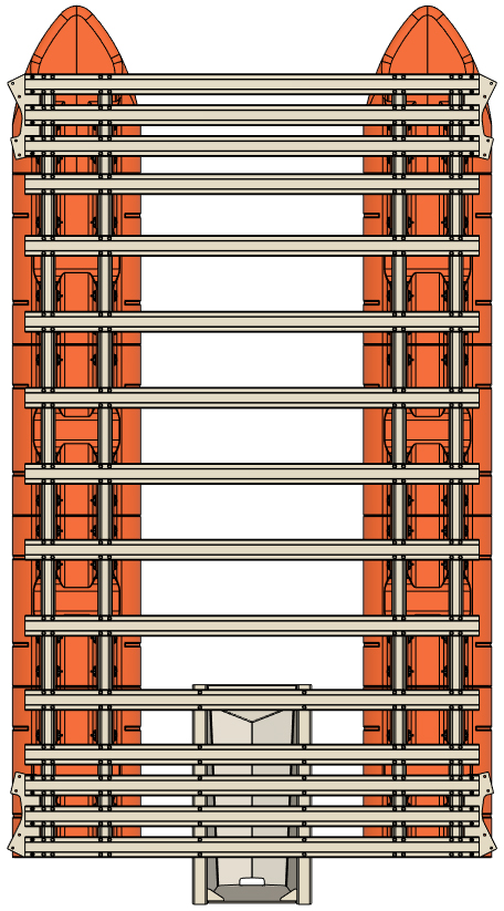
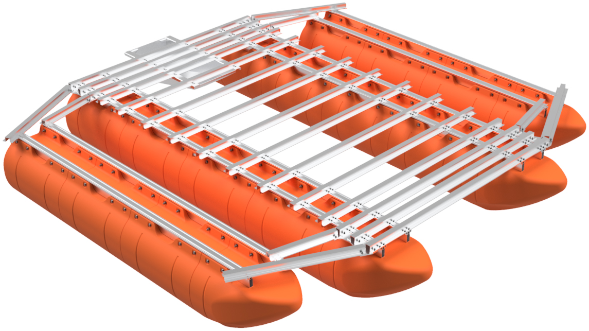
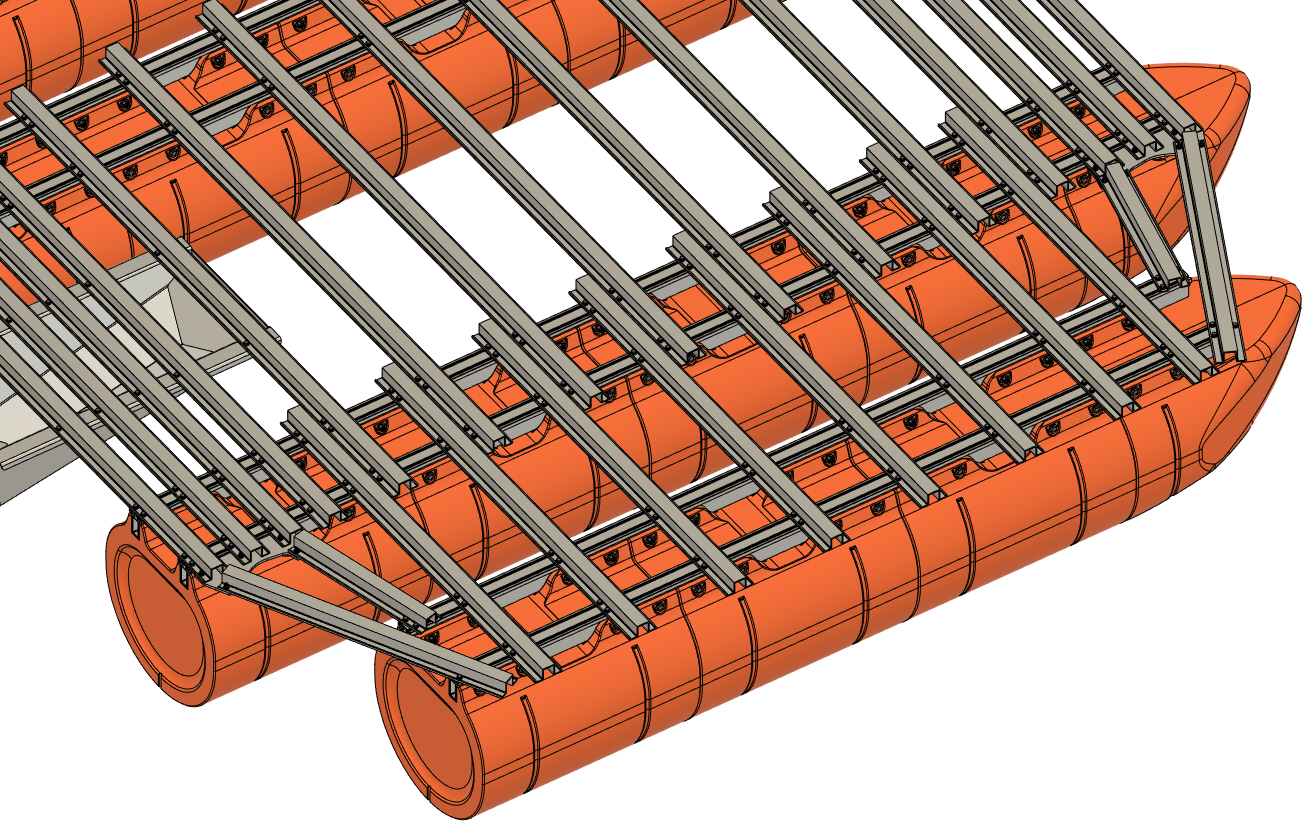
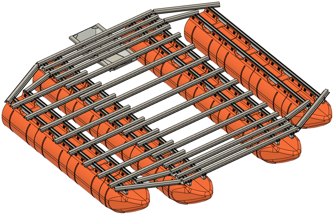
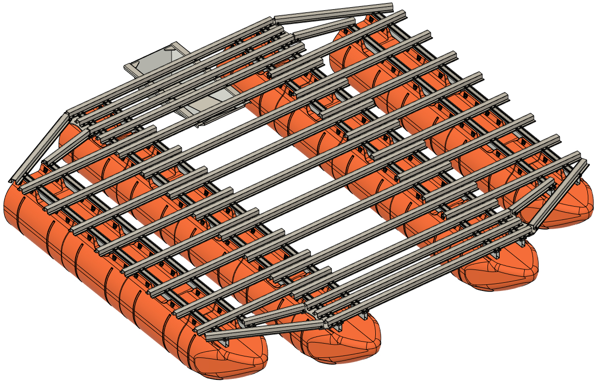
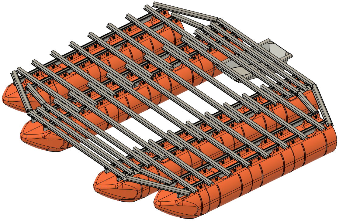
CENTRAL PLATFORM CROSSMEMBER PLACEMENT
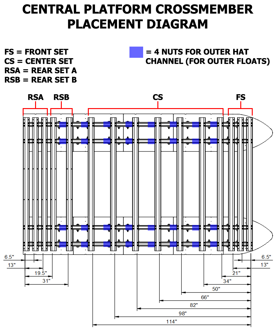
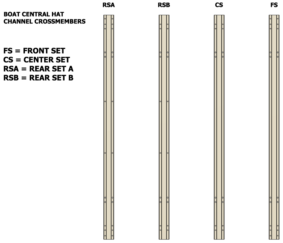
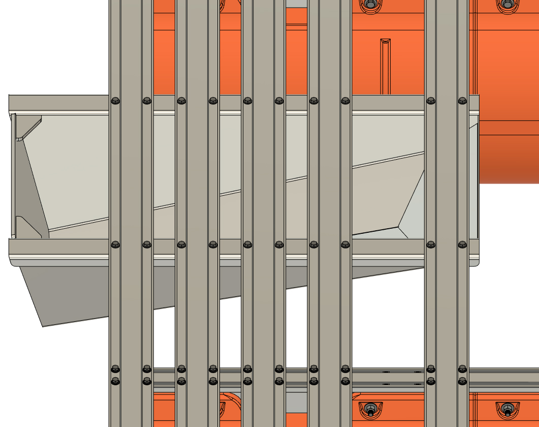
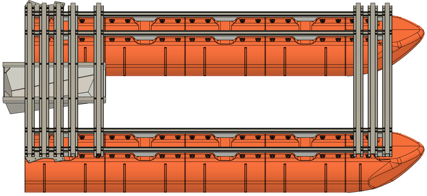
The next step is to assemble the central platform of your boat. This central platform requires that 15 hat channel crossmembers, the transom, and four 3/8" thick corner plates be installed in specific locations on top of the 15' pontoon assemblies. The central platform uses the included 8' (actually 95.75") hat channel crossmembers and there are four different bolt patterns machined into this set of parts. Below we have provided a diagram showing the four different types of 8' hat channels (bolt pattern is the only difference). The hat channel crossmembers in your kit are also labeled. To the right we have provided a crossmember placement diagram. You will have to reference this diagram throughout the remaining assembly process. We recommend printing the diagram if possible.
|
|
|
STEP 13
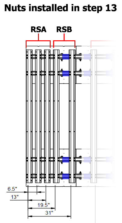
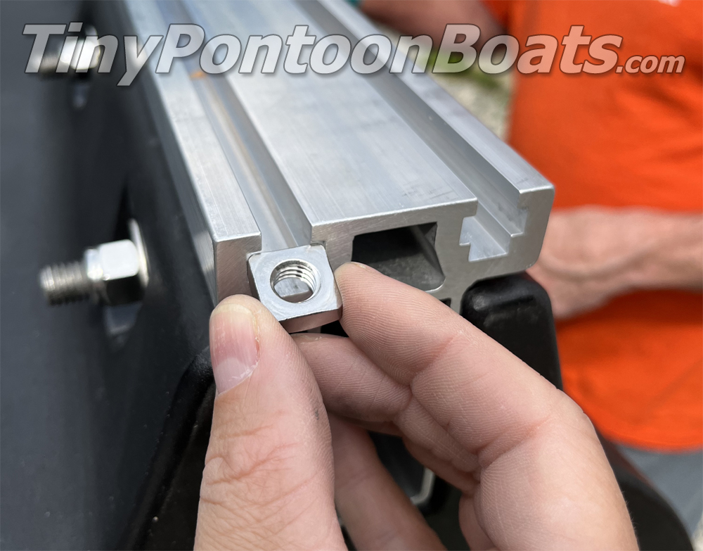
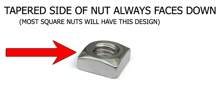
Each hat channel crossmember requires 16 sets of nuts, bolts, and washers for installation. This includes the outer crossmembers that will later attach your outer set of floats. Referencing the "CENTRAL PLATFORM CROSSMEMBER PLACEMENT DIAGRAM", slide 2 nuts into each main beam slot at the rear of the pontoon assemblies (opposite end of the nose cones) for each of the "Rear Set A" and "Rear Set B" hat channel crossmembers shown. Also, slide an additional two nuts into each slot indicated by the blue squares just rear of the frontmost "RSB" crossmember. These are for the outer platforms installed later. You will be sliding 12 square nuts into each of the slots in your 15' pontoon main beams (96 total between the two pontoon assemblies). Place the nuts in the approximate positions of the crossmembers shown on the diagram.
 |
|
|
STEP 14
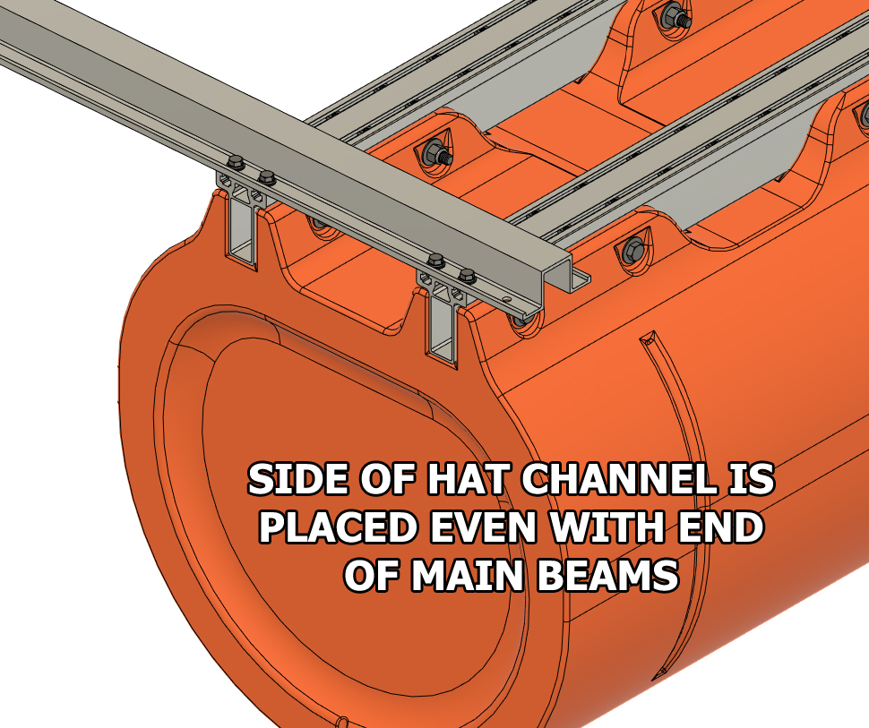
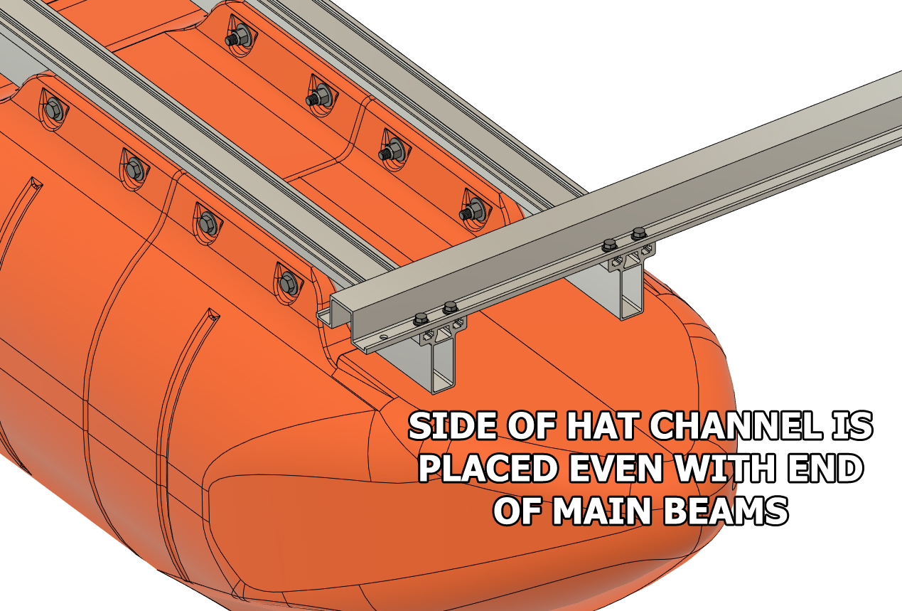
Select a "Rear Set A" hat channel crossmember and place it across the rear ends (opposite end of nose cones) of your two 15' pontoon assemblies. Using 3/8" x 7/8" hex bolts, 3/8" lock washers, and 3/8" SAE flat washers, loosely bolt it in place. The hat channel will require a total of 16 sets of bolts and washers. You will note that this crossmember will have a pair or holes on either end that extend beyond your pontoons' main beams. Adjust the hat channel so it is even with the ends of the main beams and use a square to ensure that one of the pontoon assembly main beams is square with the hat channel. Tighten the bolts on the end of the hat channel that you just squared with the pontoon (do not fully torque them yet) and leave the bolts on the other end of the crossmember loose.
NOTE:
The 8' long central platform crossmembers have "A" written on one end. Be sure to place the marked ends of the crossmembers on the same side of the boat (doesn't matter which side). When the hole pattern is machined in each crossmember, this is the end that is referenced on the machine cutting the holes. Placing the "A" end of all the crossmembers on the same side of the boat ensures perfect alignment of all the mounting holes.
|
|
|
STEP 15
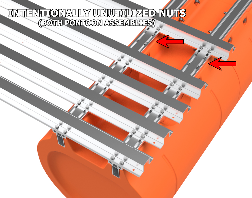
Loosely bolt on the remaining "Rear Set A" and "Rear Set B" hat channel crosmembers across the rear of your boat as shown in your diagram. Use a tape measure to ensure that the crossmembers are in the correct positions and leave the bolts very loose for the moment. Be sure to leave the group of four square nuts in each Main Beam between the two "Rear Set B" crossmembers unused for the moment. There will be a total of 16 square nuts between the two "Rear Set B" crossmembers (includes both pontoon assemblies). Verify that the side of the rearmost hat channel crossmember is even with the end of the main beams on both pontoon assemblies and tighten (do not fully torque) the rearmost hat channel bolts that were not tightened in the last step.
|
|
|
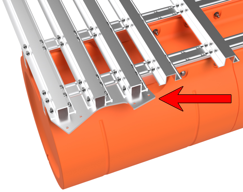
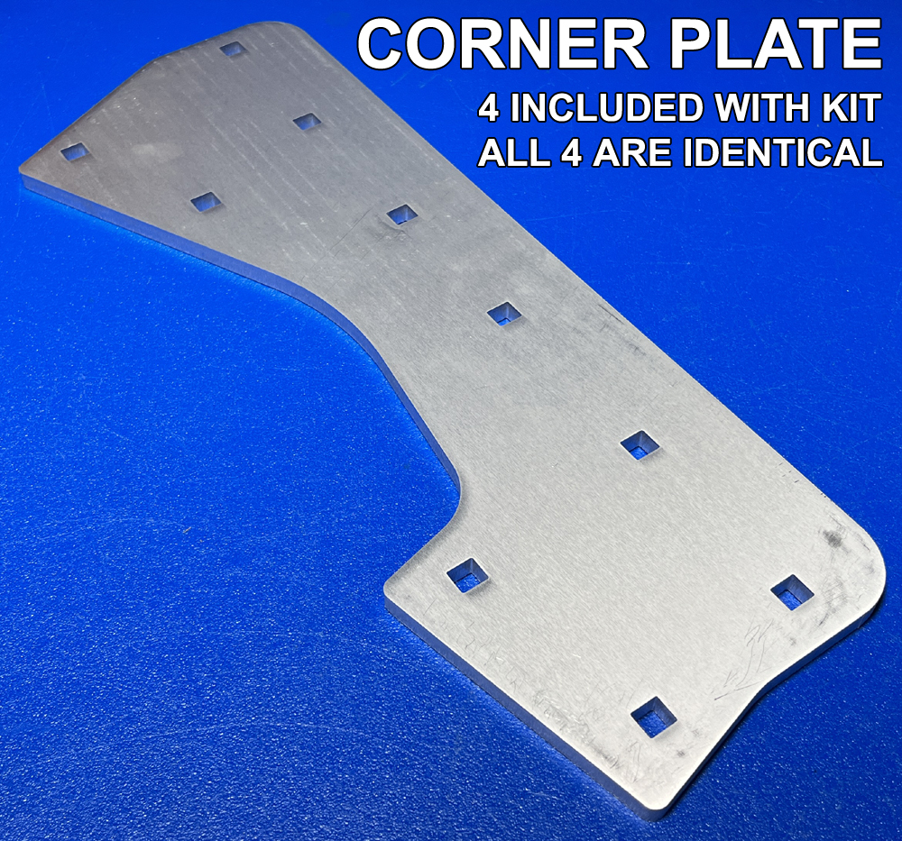
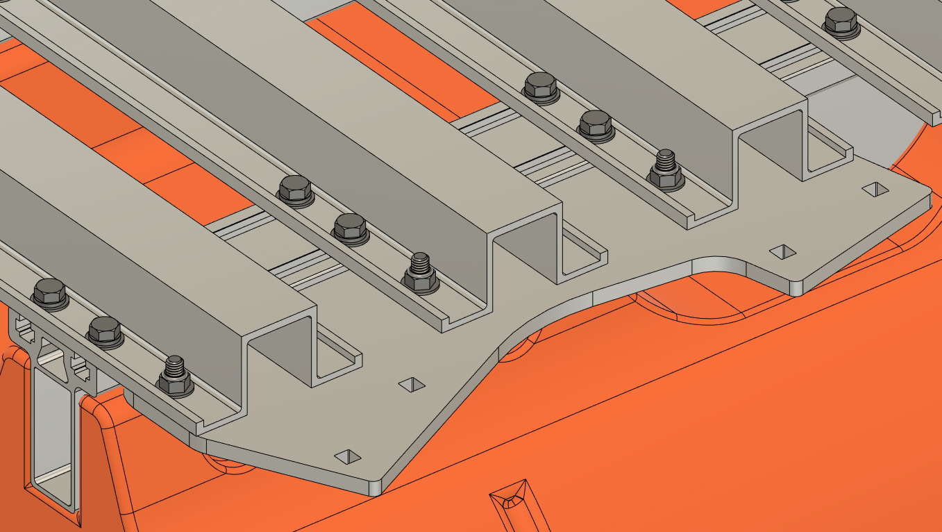
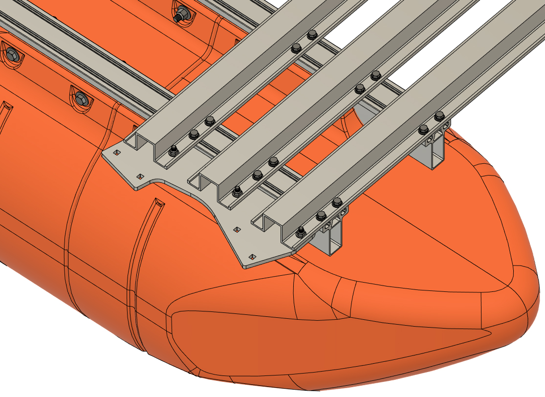
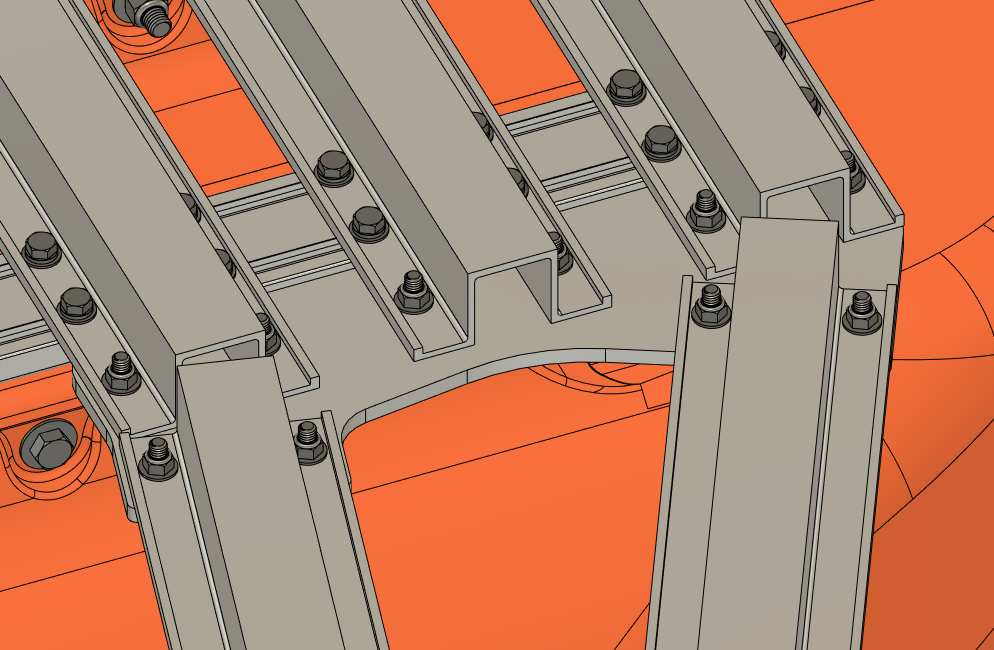
STEP 16
Your frame system includes four 3/8" aluminum plates that have a total of 10 small square holes. These four plates are identical and we will refer to them as the "Corner Plates" from this point foward. Locate two of the these plates and the bag of hardware labeled "Corner Plate Hardware" or similar. The bag of hardware will include 3/8"x1 1/4" carriage bolts and 3/8" flange lock nuts. On both rear corners of the platform, loosely bolt one of these plates under the ends of the "Rear Set A" hat channels that you have installed. Be sure to reference the pictures to the right to match the installed orientation of each plate. Installation requires six bolts and nuts per plate. Bolts insert through the underside of the plate and through the outer holes in the hat channels. The nuts land on the upper side of the hat channel flanges as shown. Do not fully tighten the nuts and bolts yet.
|
|
|
STEP 17
This step is much easier with a helper, but if you are working alone, a ratchet strap can be used to pull the transom against the bottom of the boat to start your installation.
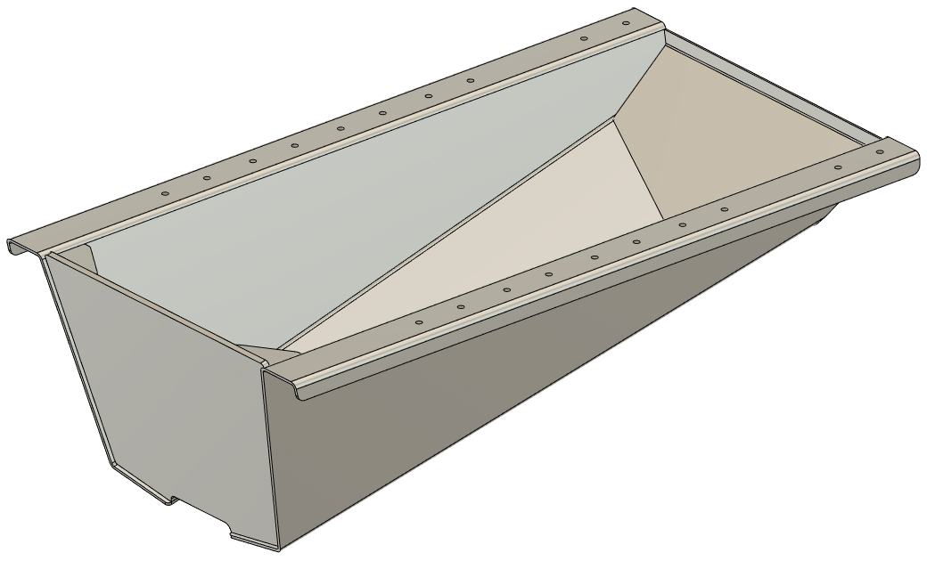
Locate the transom and the bag of hardware labeled "Transom Hardware" or similar. Select 3/8" x 1 1/4" hex bolts and SAE flat washers from the bag, and insert the bolts with washers through the four central holes in each of the Rear Set crossmembers (A and B). The bolts will now be hanging down through the hat channels. Bring the transom under your boat and lift it up against the frame, aligning the holes in the transom mounting flanges with the hanging bolts. Holding the transom in place, loosely install 3/8" flange locknuts from the transom hardware bag onto the bolts from the underside of the transom. Loosely tighten all the bolts, but do not fully torque them yet. Your transom should now be fastened by a total of 20 nuts and bolts. To make this task easier, you can apply a little bit of Loctite to the threads of each nut before threading it on. This is not 100% necessary, but can make this step go more smoothly.
|
|
|
STEP 18
From the front of your boat (nose cone end), slide a quantity of 34 of the 3/8" square nuts into each main beam slot (both pontoon assemblies). Referencing your "Central Platform Crossmember Placement Diagram", place the nuts in each main beam in groups of four (two per slot) so they are placed in the approximate positions of the of the remaining crossmembers and blue squares shown on your diagram.
Double and triple check that you have 34 nuts in each slot (ahead of the Rear Set B crossmembers). If your count is incorrect, this will cause problems during the remainder of your assembly.  |
|
|
STEP 19
Select a "Front Set" 8' hat channel crossmember and place it across the front ends of your main beams. Using 3/8" x 7/8" hex bolts, 3/8" lock washers, and 3/8" SAE flat washers, loosely bolt it in place as you have prior hat channels. You will note that this crossmember will have a pair or holes on either end that extend beyond your pontoon main beams. Adjust the hat channel so the side is even with the ends of the main beams and secure the bolts. Do not fully torque the bolts yet.
|
|
|
STEP 20
Referencing your "CENTRAL PLATFORM CROSSMEMBER PLACEMENT DIAGRAM" for positions, place the remaining two "Front Set" crossmembers across your pontoons. Loosely bolt the crossmembers down with the same 3/8" bolt sets as before.
|
|
|
STEP 21
Locate the two remaining corner plates and bag of corner plate hardware. Bolt a plate on either end of the "Front Set" crossmembers as you did prior in step 16. This time, the taper on the plates faces the opposite direction as in step 16 (tapered backwards as shown). Secure the nuts and bolts, but do not fully torque them yet.
|
|
|
STEP 22
Referencing your "CENTRAL PLATFORM CROSSMEMBER PLACEMENT DIAGRAM", work from the front rearward and install the "Center Set" crossmembers onto your boat using the same 3/8" bolt sets. Double-check all your measurements for placement of the "Center Set" hat channels and secure the bolts, but do not yet fully torque the bolts. Remember that each main beam MUST have a set of 4 square nuts that are currently unused behind each of the "Center Set" hat channels. With all your hat channels in place, double-check that this is the case. Remember, every blue square on your "CENTRAL PLATFORM CROSSMEMBER PLACEMENT DIAGRAM" indicates a total of 4 square nuts that are loose in the main beams at this point. DOUBLE AND TRIPLE CHECK that this is the case before moving on.
|
|
|
STEP 23
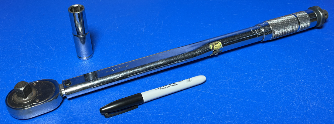
All of your central platform frame parts are now bolted onto the boat, and all the bolts are fairly loose at this point. Using your 1/2" drive torque wrench and a deep 9/16" socket, work from the front to the rear end of the boat and torque EVERY 3/8" frame bolt you've installed up to this point to 55 foot pounds. DO NOT TORQUE BEYOND THIS. If you over-torque and break a bolt at this point, much disassembly will be required to fix the error. After you have torqued a bolt, draw a line across it so you can easily keep track of what has been torqued. After you've torqued all of the hat channel and corner plate bolts, move onto the transom bolts. TORQUE YOUR TRANSOM BOLTS FROM UNDER THE BOAT and, if possible, have a helper use a wrench to hold each bolt head from above the boat.
Double-check that every nut and bolt on your frame has a line drawn on it indicating that it has been torqued to specification. Your central pontoon platform is now completed.
|
 |
|
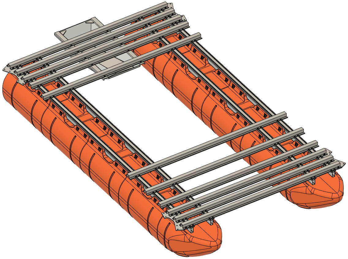
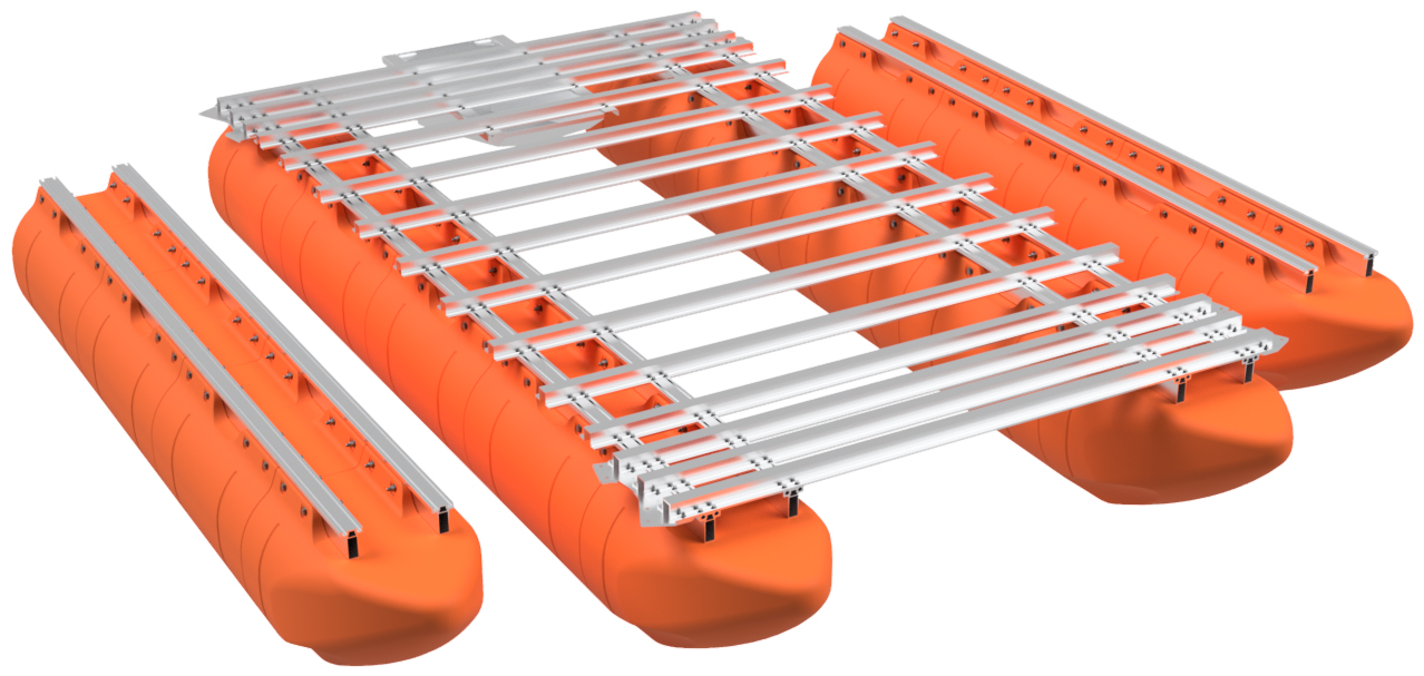
STEP 24
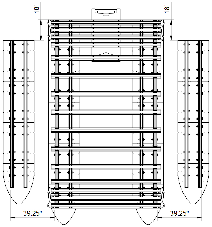
With the central platform completed, place a 12' pontoon assembly on either side of the boat. Offset each 12' pontoon so that it is approximately 13 1/2" away from the adjacent 15' foot pontoon as shown (39.25" center-to-center). Adjust the placement of each 12' pontoon assembly so that the rear end is 18" ahead of the rear end of the central platform pontoons (do not measure from transom). As you assemble the rest of the boat, the 12' pontoon assemblies will self-align.
|
|
|
STEP 25
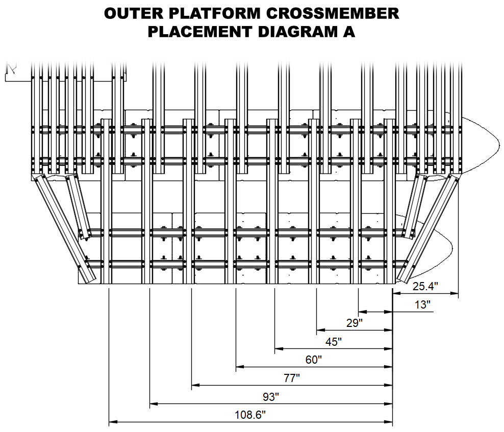
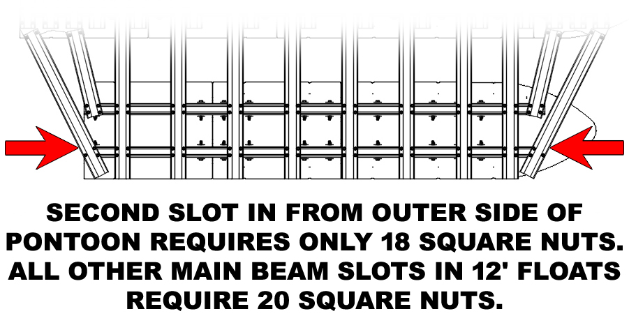
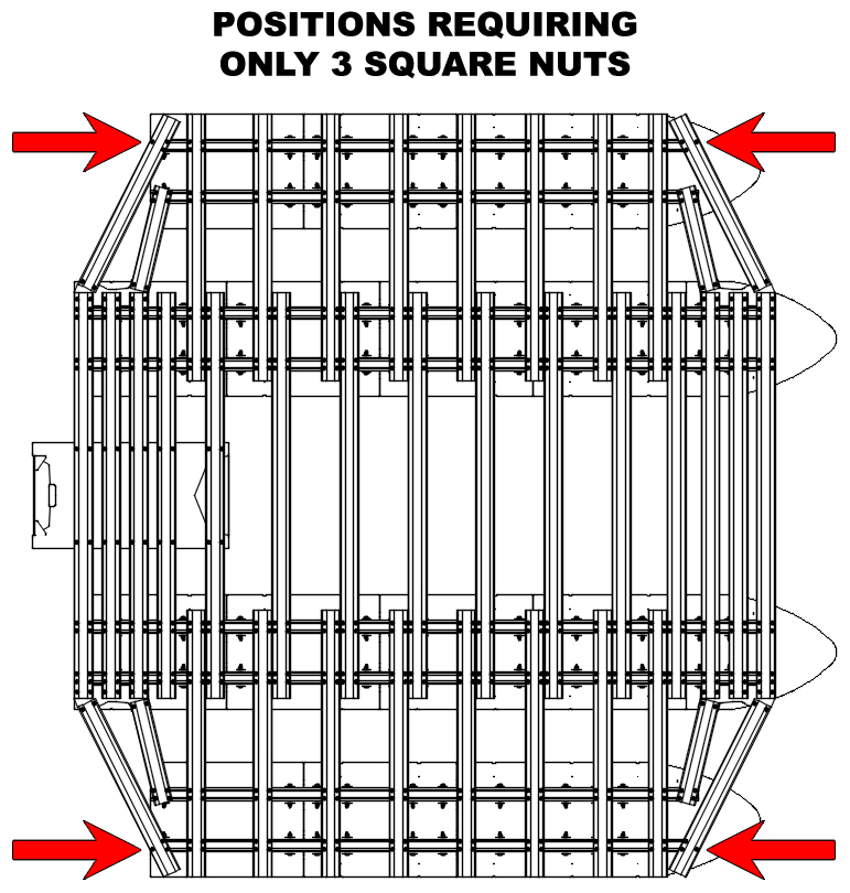
Referencing the "OUTER PLATFORM CROSSMEMBER PLACEMENT DIAGRAM A" to the right, insert 3/8" square nuts into each of the 12' pontoon main beam slots. For each position that a hat channel crossmember attaches to the main beams, 4 square nuts are required, EXCEPT for the outermost corners of the 12' floats. This position requires only 3 nuts. This means that you are sliding 20 or 18 square nuts into each main beam slot. The diagram below clarifies this. Do this for both 12' pontoons and slide groups of 4 square nuts into the approximate positions of each hat channel connection (except for the outer corners, which only require a group of 3 square nuts). Double-check that you have the appropriate number of square nuts in each main beam.
|
|
|
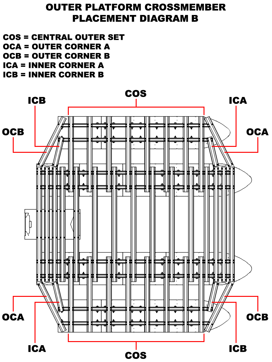
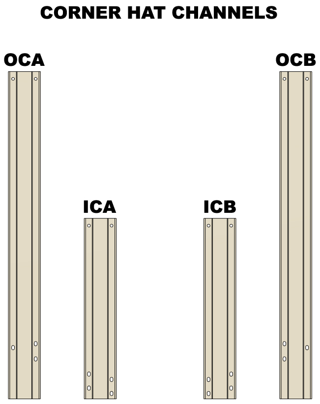
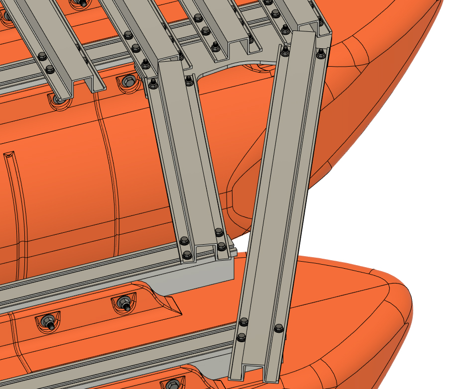
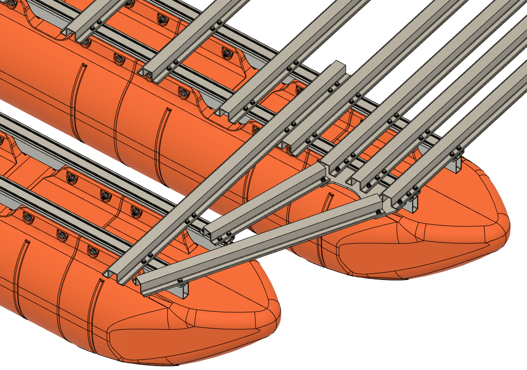
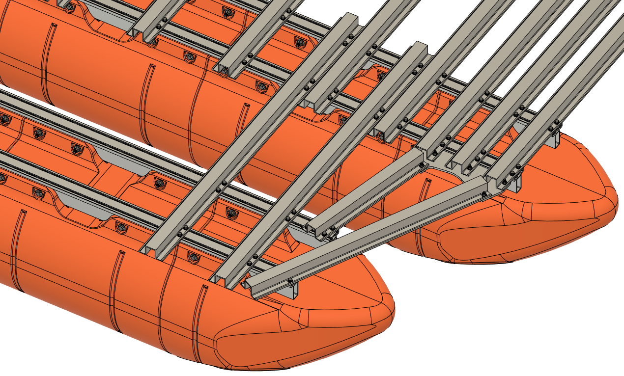
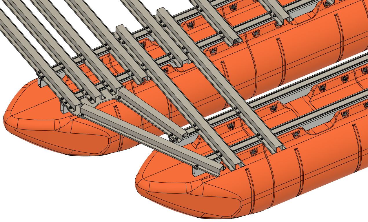
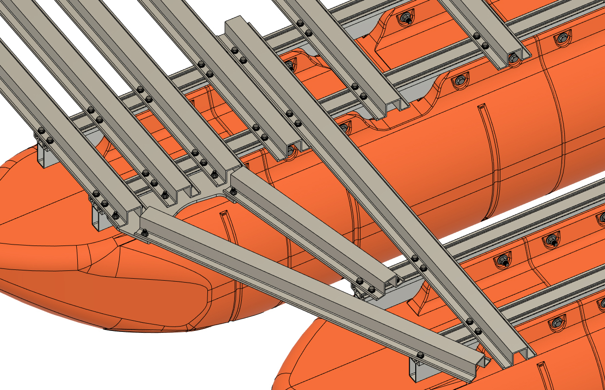
CORNER HAT CHANNEL NOTE
Your kit includes a total of 8 short hat channels that attach to the previously installed corner plates and the ends of the 12' pontoon main beams. The kit includes two different "Outer Corner" hat channels (each 44 7/8" long) and two different "Inner Corner" hat channels (each 24 3/4" long). The parts will be labeled with the three letter code shown below and are to be installed at the corners of the boat shown in the "OUTER PLATFORM CROSSMEMBER PLACEMENT DIAGRAM B" to the right.
|
|
|
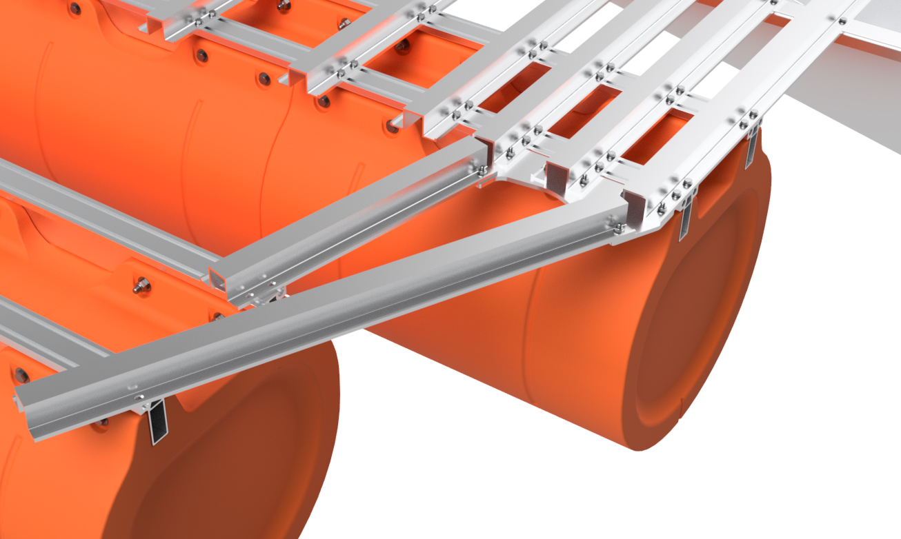
STEP 26:
As you did prior, use the 3/8"x1 1/4" carriage bolts and 3/8" flange lock nuts from the bag labeled "Corner Plate Hardware" and loosely bolt the corner hat channels to each corner plate on the boat. The end of the hat channels with only two holes bolt to the plates. Visually check that the holes on the outer ends of the hat channels will line up with the slots in the 12' pontoon. If they do not, the wrong corner hat channel has been selected. Do not fully tighten the nuts and bolts yet.
|
|
|
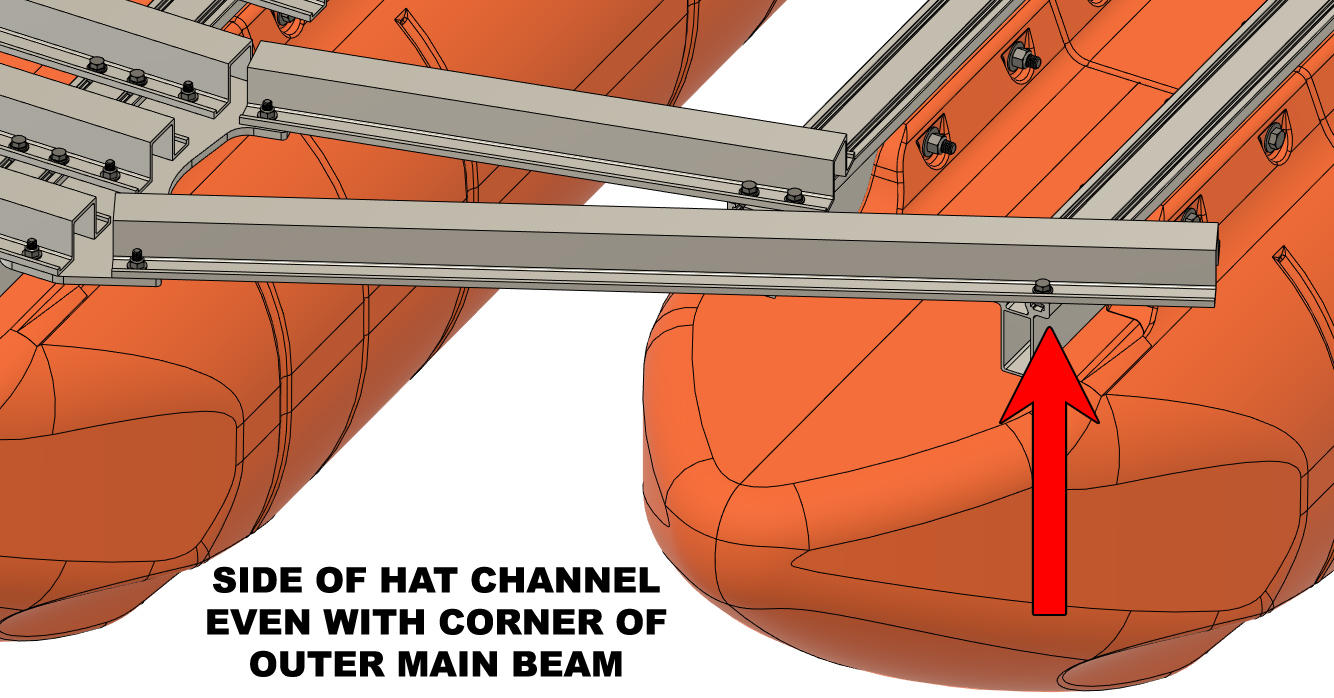
STEP 27:
Using 3/8" x 7/8" hex bolts, 3/8" lock washers, and 3/8" SAE flat washers, loosely bolt all 8 of the corner hat channels to the 12' pontoon assemblies. Adjust the placement of the 12' floats as necessary so that the sides of the outer corner hat channels are even with the outer corner of the outer main beams on the 12' floats. Do this for both sides of your boat. Do not fully tighten the bolts yet.
|
|
|
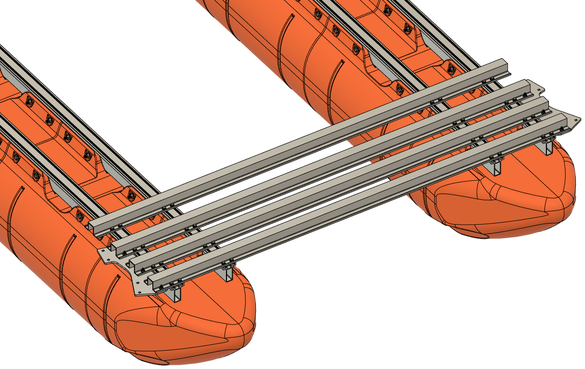
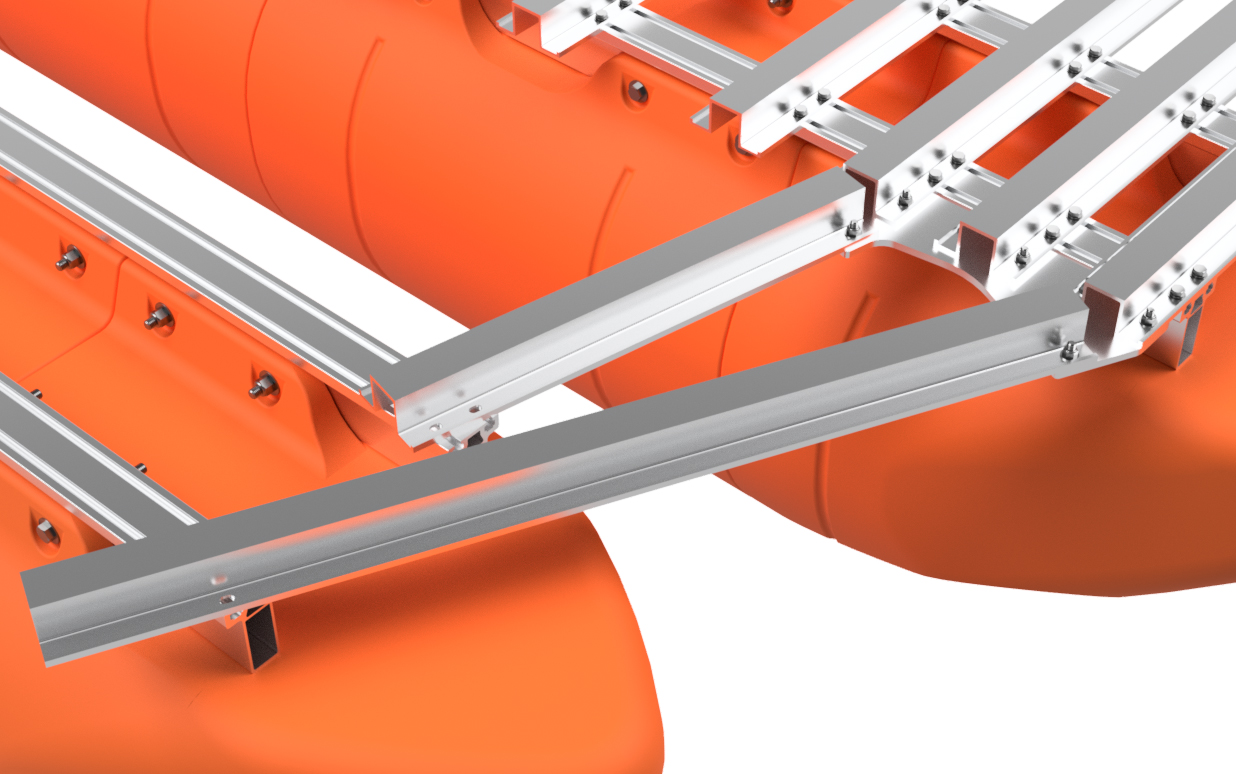
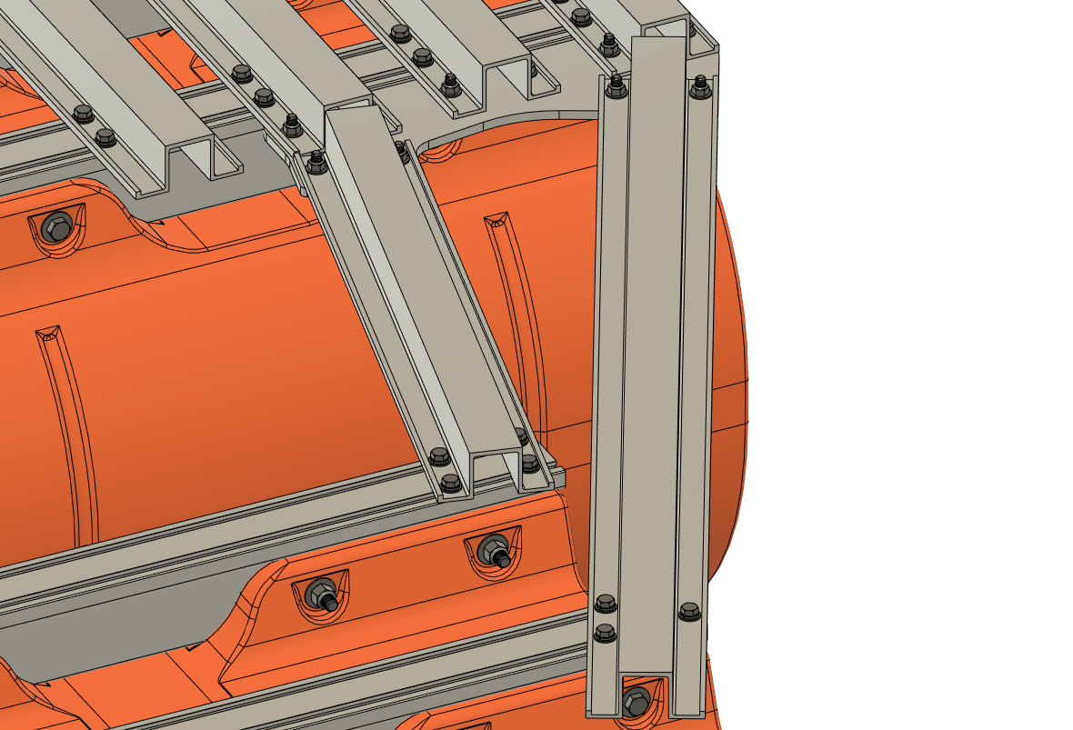
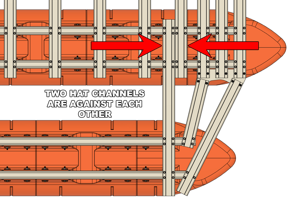
STEP 28:
The only hat channels remaining in your kit are the "Central Outer Set" crossmembers. These hat channels are all identical and 63" long. The hole pattern for these crossmembers is offset and the end that extends furthest from the holes is placed on the outer side of the boat. When installed, the outer end of each "Central Outer Set" crossmember will be approximately even with the side of the outer floats.
Using 3/8" x 7/8" hex bolts, 3/8" lock washers, and 3/8" SAE flat washers, loosely bolt the frontmost "Central Outer Set" hat channel (position shown on "OUTER PLATFORM CROSSMEMBER PLACEMENT DIAGRAM A") between the 15' and 12' pontoon on one side of the boat. You will note that the hat channel you are installing goes right against a hat channel on the central platform. Leave the bolts only finger tight for now. 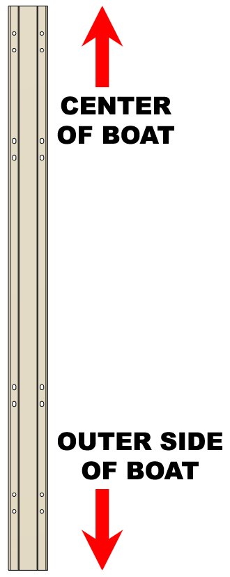 |
|
|
STEP 29:
Referencing the crossmember diagram, working your way backward on the same side of the boat, install the remaining "Central Outer Set" crossmembers. Continue to leave the bolts finger tight for now.
|
|
|
STEP 30:
Repeat steps 28 and 29 for the opposite side of the boat. Be sure to start at the front and work your way to the rear of the boat as you install the hat channels.
|
|
|
STEP 31:
All of your outer platform frame parts are now bolted onto the boat, and all the bolts are fairly loose at this point. Using your 1/2" drive torque wrench and a deep 9/16" socket, work from the front to the rear on both sides of the boat and torque EVERY 3/8" frame bolt you've installed on the outer portion of the boat to 55 foot pounds. DO NOT TORQUE BEYOND THIS. If you over-torque and break a bolt at this point, much disassembly will be required to fix the error. Just as before, after you have torqued a bolt, draw a line across it so you can easily keep track of what has been torqued.
Double check that every 3/8" bolt on the boat has a line drawn across it indicating that it has been torqued to specification.
|
|
|
YOUR KIT IS COMPLETED!
Let's be honest, that was a lot of work and you did a great job! Your frame and floats kit assembly has been completed, so take a break and dream about what you'll build on top.
|