|
603-630-5658
|
|
tinypontoonboats@gmail.com
|

|
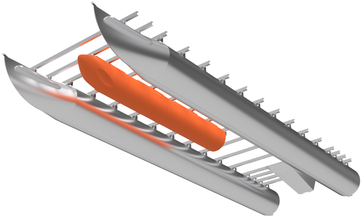
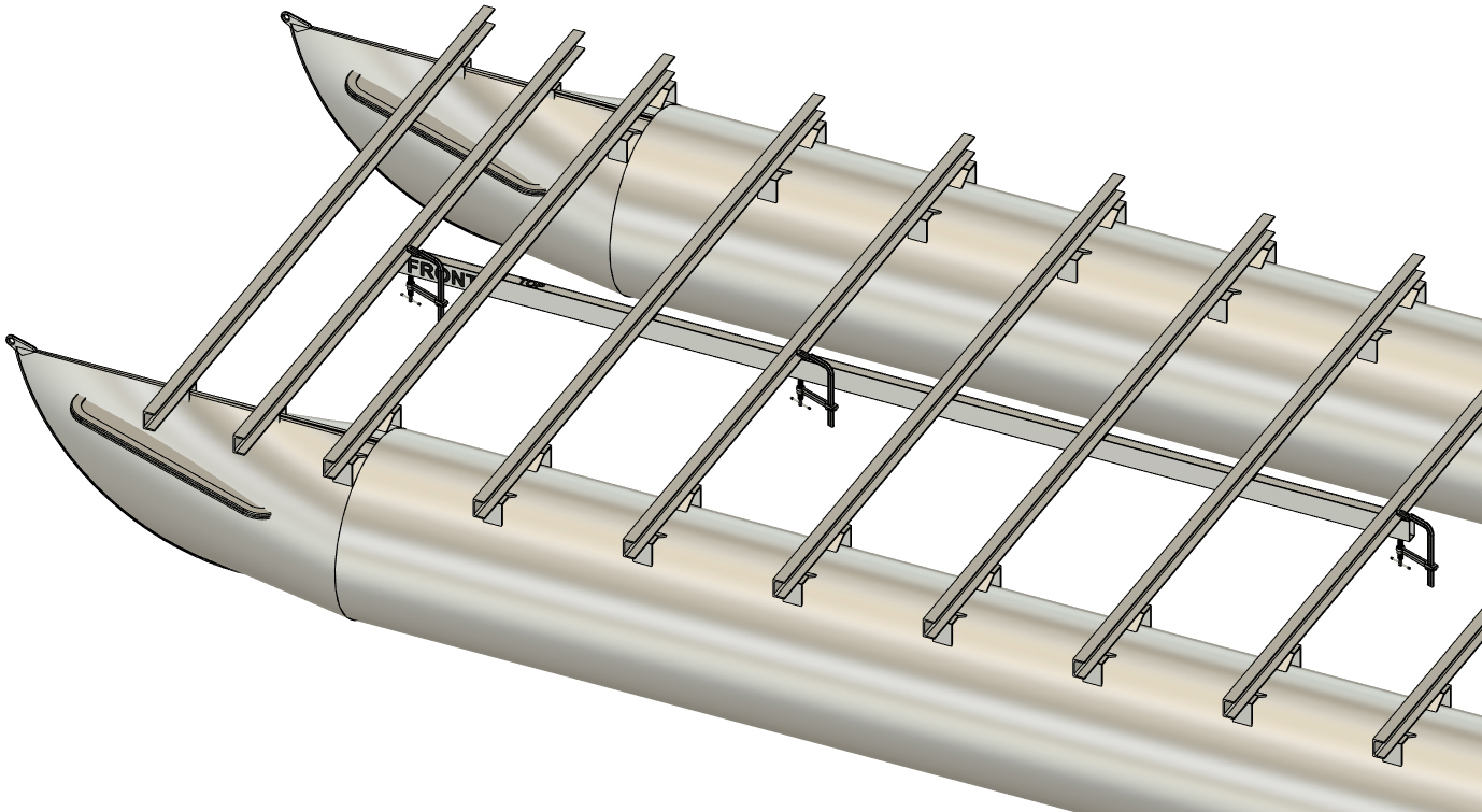
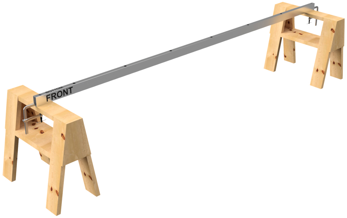
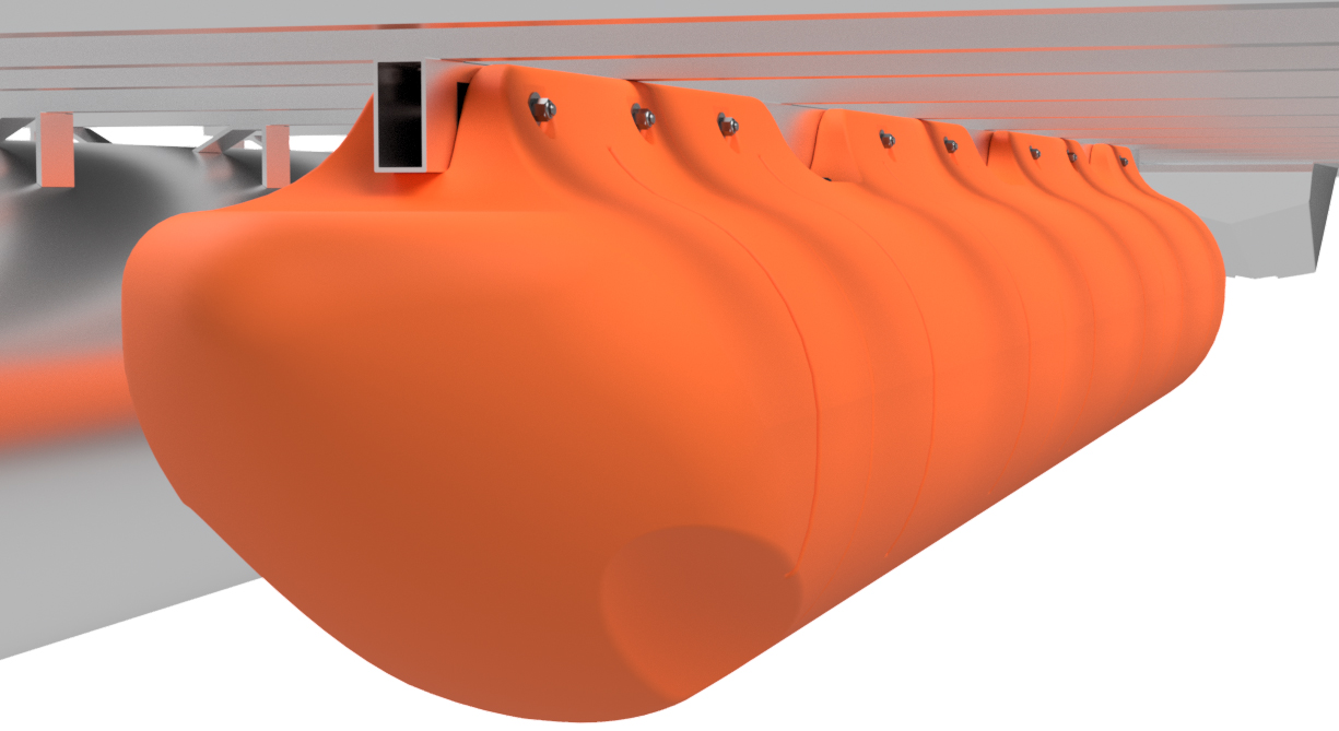
The intention of this page is to provide a general set of instructions for installing a third row of our 18" wide plastic pontoons on other brands of boats. The example boat that we show in these instructions is a 8'x18' boat with 20" diameter aluminum pontoons and C-channel crossmembers. There are many different pontoon boat frame arrangements and we cover different crossmember styles below. The procedure we've laid out is not the only way to install a row of our floats under your existing boat, but it is what we've found to be the easiest way. Depending on your arrangement, you may have to space the pontoon assembly down from the frame, mount it in an alternate location, or modify your approach in any number of ways. We simply can't cover all pontoon boats that exist, so this set of instructions covers a simple installation of a 11' row of 18" wide floats under our example boat. We show mounting the pontoon assembly as high as possible as well. The end user will need to adapt their approach to their particular boat, but everything included on this page will apply to most applications.
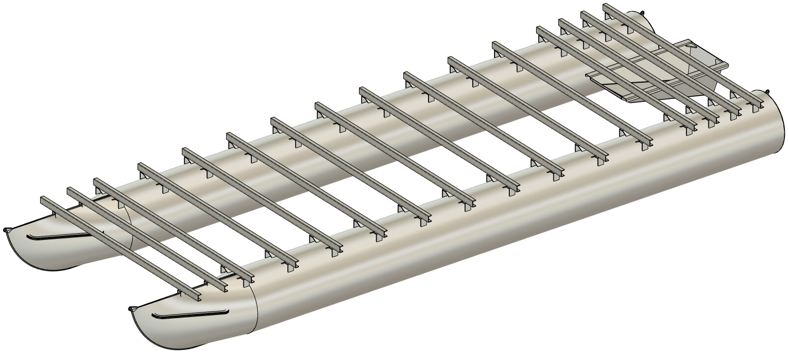
Only the frame and floats are shown on our example boat. This is to provide as much clarity as possible. When working under your boat, special care is required to avoid injury. Please watch your head and keep the skin on your knuckles! |
|

|
REQUIRED MATERIALS, HARDWARE, & TOOLS
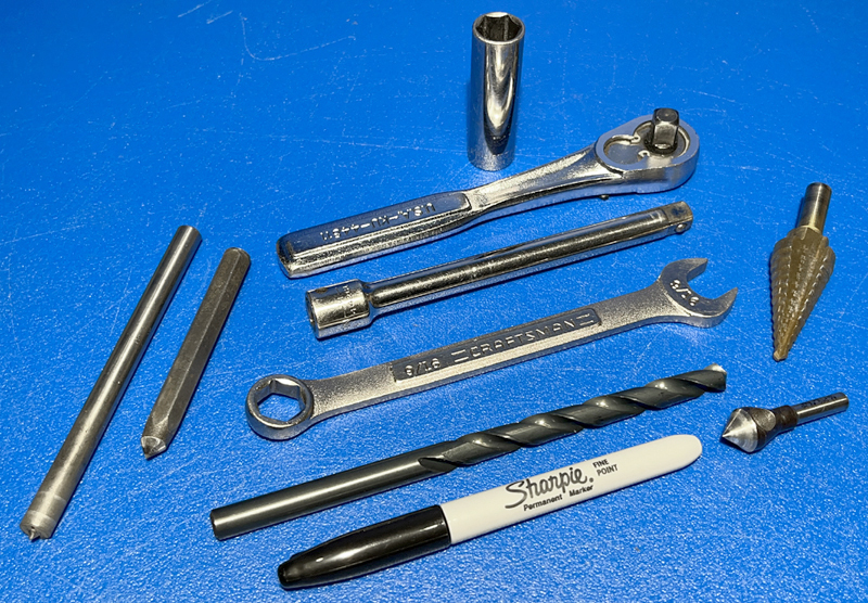
When only purchasing floats from Tiny Pontoon Boats, you will receive just that: floats. If you are mounting our 18" wide floats under your existing boat, you will require a length of rectangular aluminum tube (if mounting in a similar fashion as depicted) and certain hardware. Below is list of the recommended material and hardware, as well as our favorite sources for them. Further below is a list of the tools required for the task with links to the somewhat specialized tools from McMaster (our favorite industrial supplier) and Amazon. Click on the part number or Amazon link to view the item. Many customers will already have the majority of these tools, if not all of them. These tools (other than perhaps the transfer punch) should be stocked at your local home supply or hardware store as well.
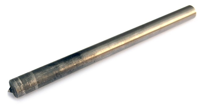
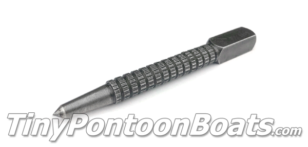
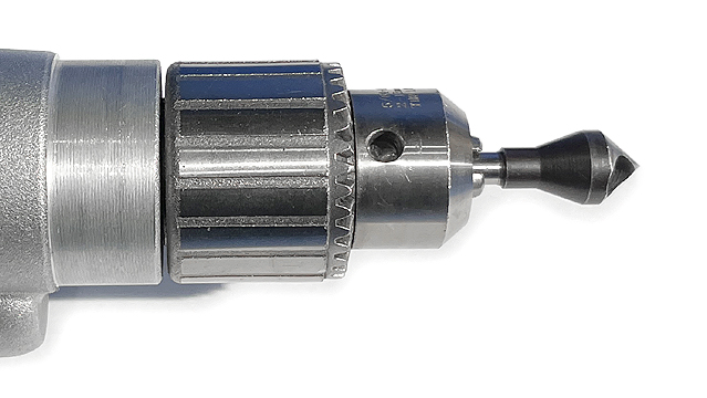
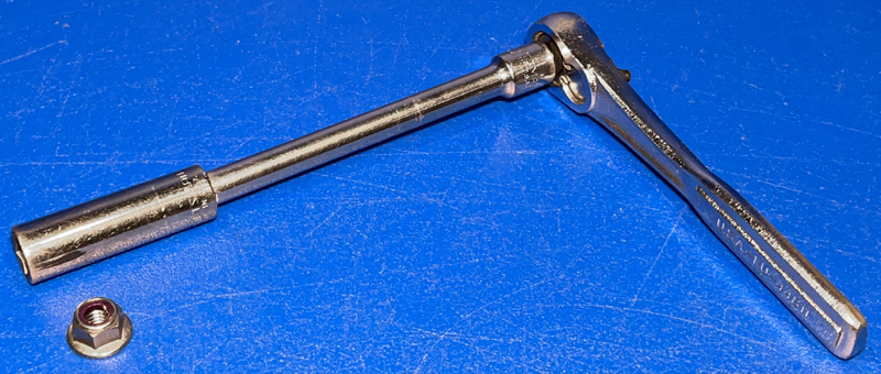
REQUIRED TOOLS:
MOUNTING TUBE & HARDWARE:
|

|
|
STEP 1
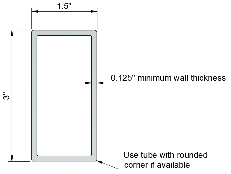
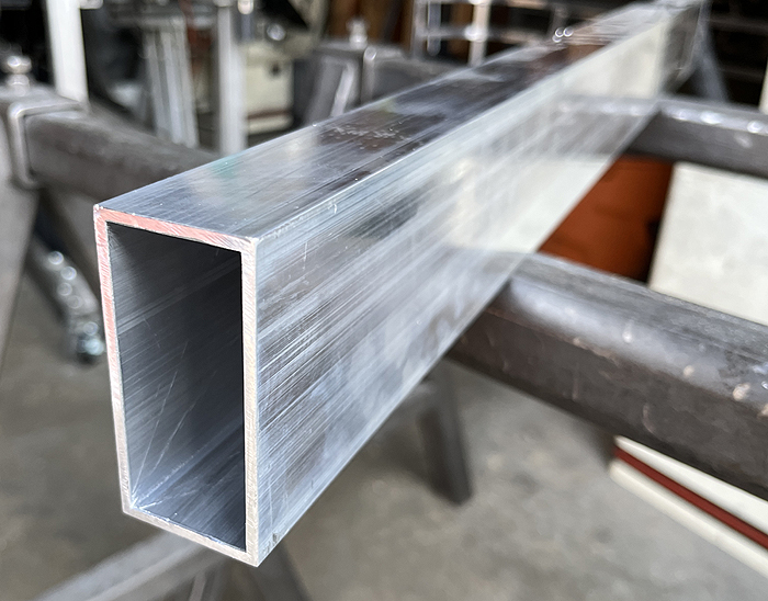
The aluminum tube required for installing our 18" wide plastic floats is a 1.5" x 3", 0.125" wall aluminum tube. The material we recommend is available through OnlineMetals.com as listed in the table in the section above. If ordering locally, ask for "radius corner" tube if it is available. As of yet, we have not been able to find a rounded corner tube this size sold online. Before purchasing your mounting tube, you'll need to know how long your tube needs to be. Below we have provided a table showing minimum tube length requirements for different float arrangements. We say minimum because your boat may require longer lengths to securely fasten the tube in place. We cover that below.
MINIMUM MOUNTING TUBE LENGTHS:
|
|
|
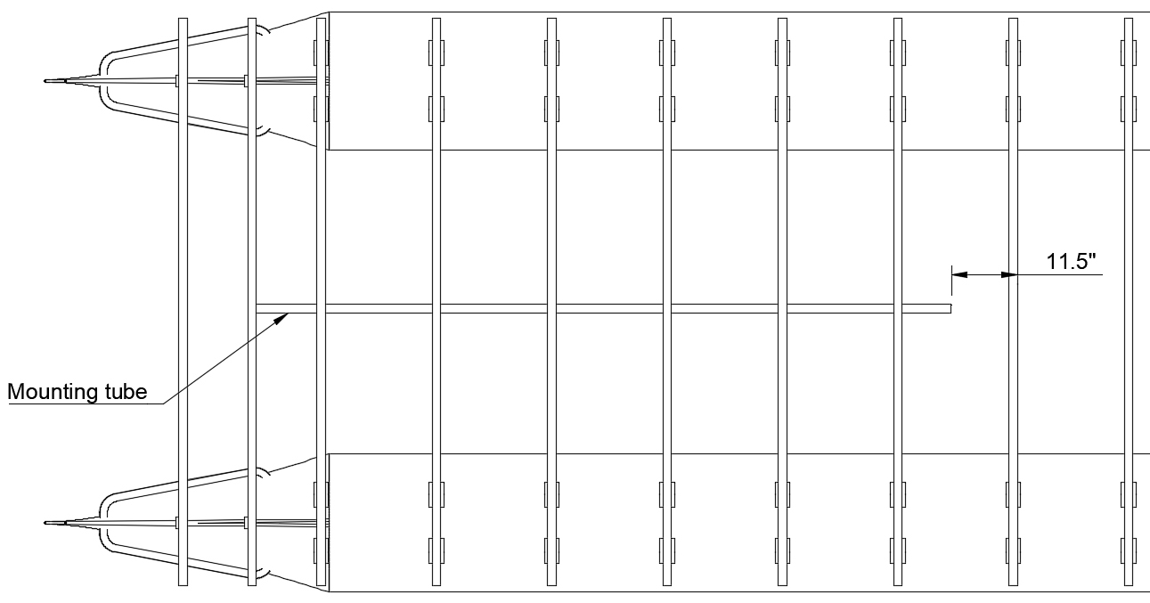
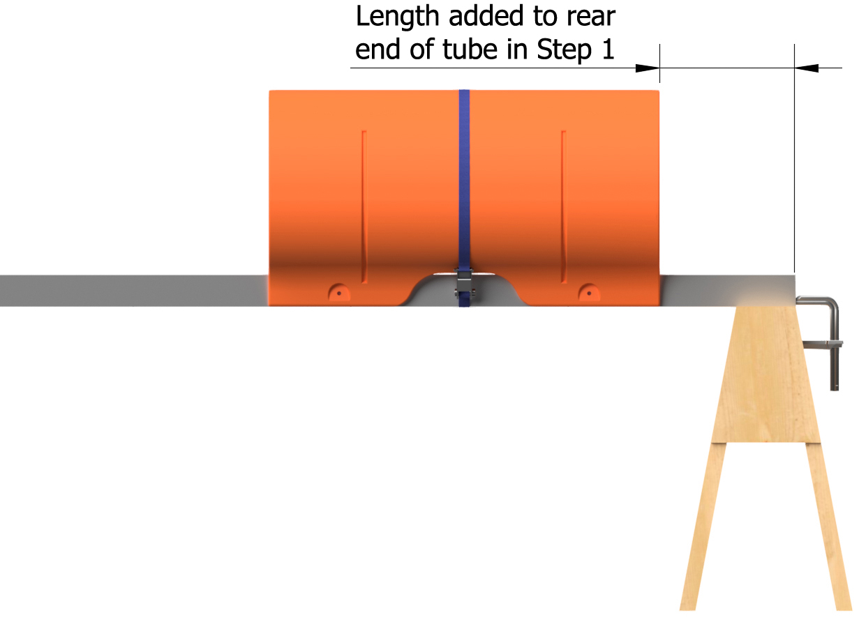
The length of the required mounting tube is determined both by the length that your floats require and where it must attach to your frame. We recommend having the mounting tube extend 1" beyond the edge of the crossmember beyond where the new pontoon assembly's minimum tube length ends. Our example is listed below for clarity.
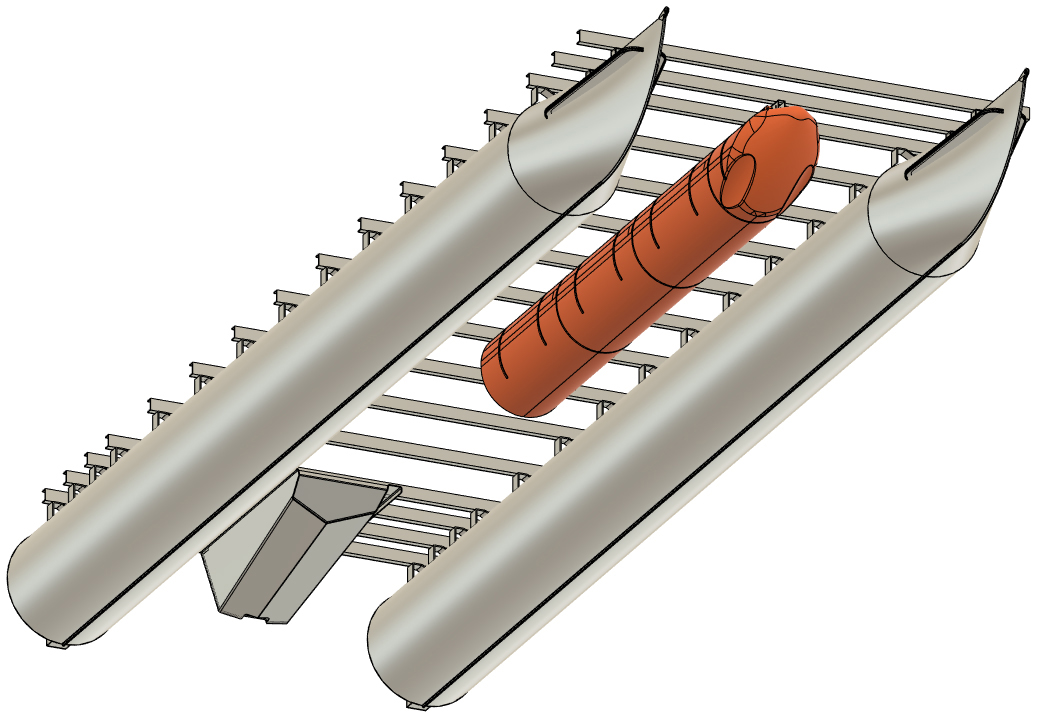
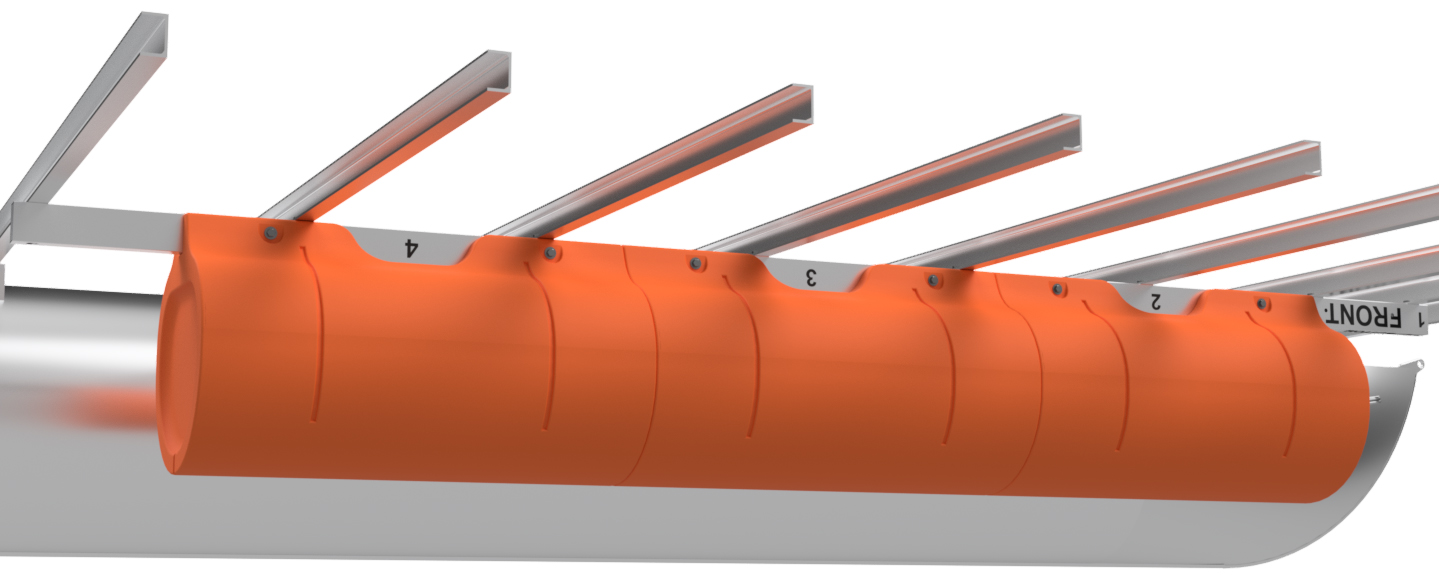
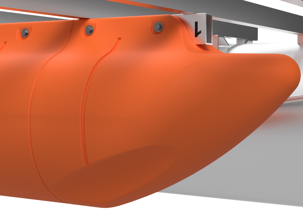
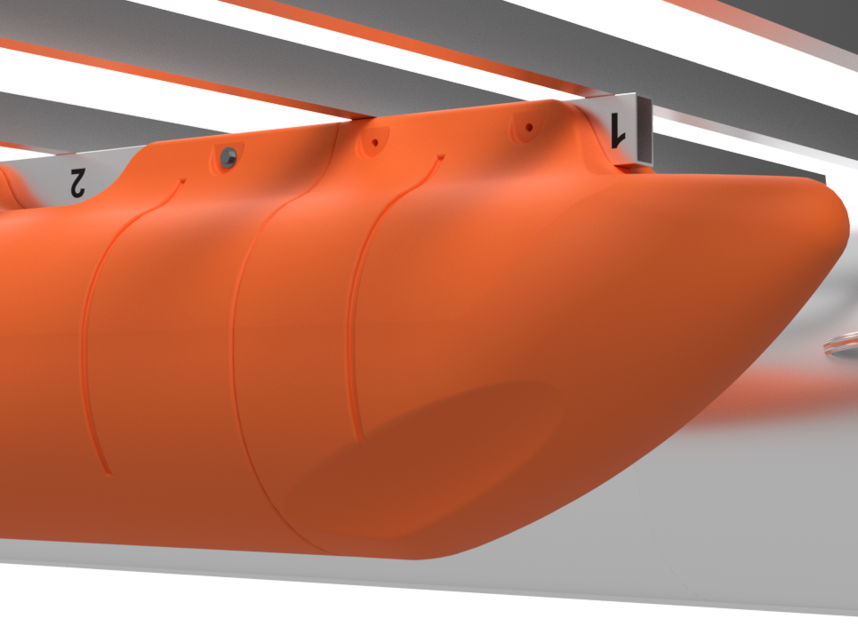
As mentioned above, in this set of instructions, we're showing installation of a 11' long single-nose set of floats under a 8'x18' boat. With this installation, we're placing the nose cone just about even with the front of the boat's deck. As the minimum length of mounting tube for this set of floats is 122", and the set of floats are 11' overall (nose cone extends 10" beyond minimum tube length), we are attaching the mounting tube to the second crossmember in from the front of the boat and extending toward the stern. The diagram below to the left shows where the tube would land with the minimum length from the table above. With our boat, we have to add 1" to the front end and 12.5" to the rear end of our mounting tube to extend 1" beyond the crossmembers we are attaching to. This means that our mounting tube must be 135.5" long overall (122" + 1" + 12.5"). The diagram to the lower right shows where our 135.5" long tube is to be mounted. |
|

|
|
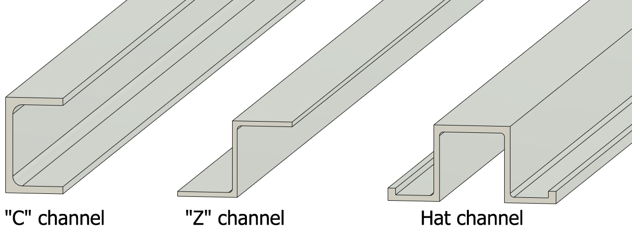
FRAME CROSSMEMBER TYPES
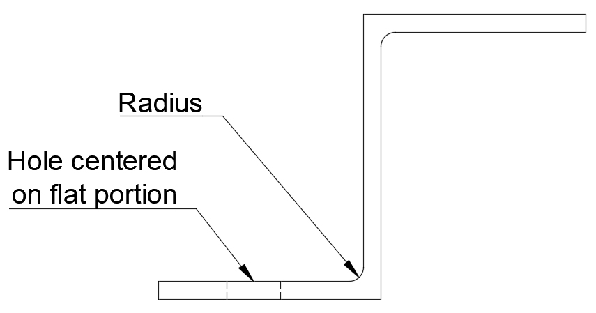
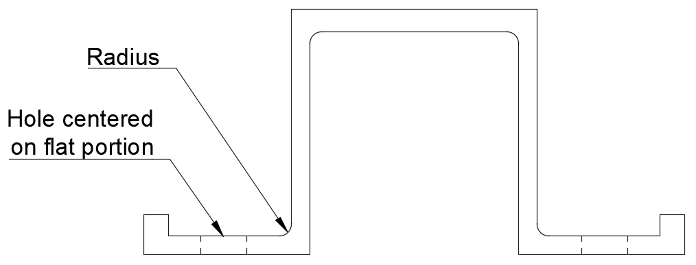
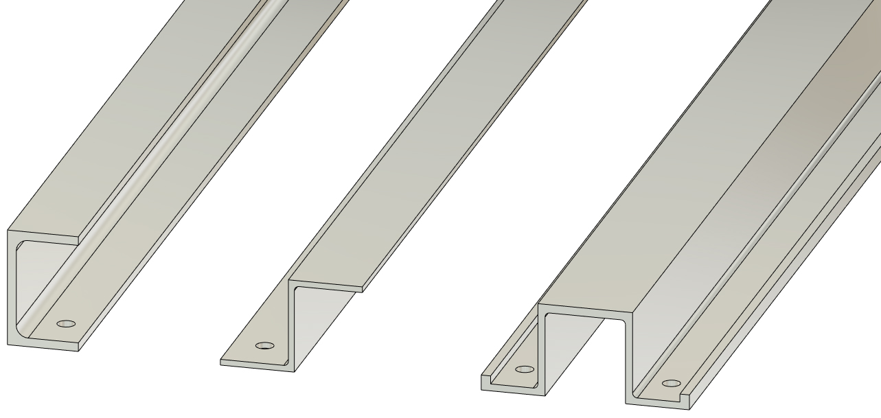
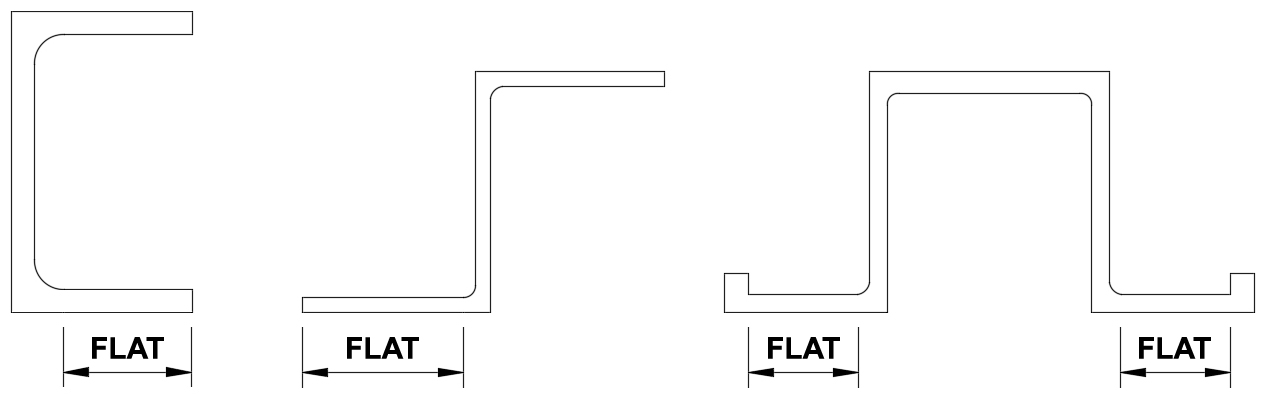
Each pontoon boat manufacturer uses their own style of frame crossmembers, but there are three basic profiles we usually see. Crossmembers are typically a "C" channel, "Z" channel, or hat channel. The frame systems for our boat kits use hat channel (provides the most rigid design, while allowing for ease of assembly). There are also a few boats that have fully enclosed rectangular tube crossmembers. If your boat has these, the only option is to weld the mounting tube under your boat unless you intend to replace your decking (plywood or otherwise). We will not cover this type of installation.
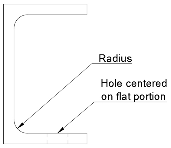
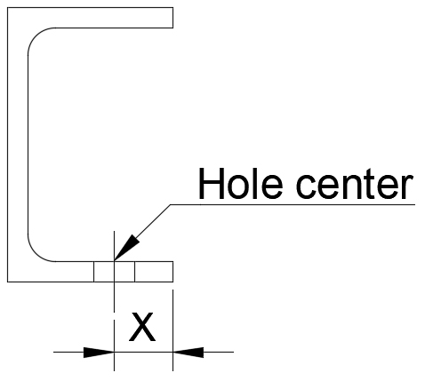
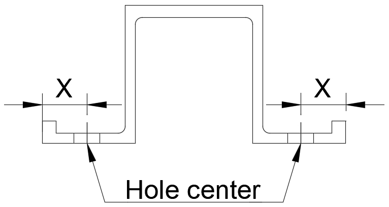
When working with any of the channel type crossmembers, the goal is to locate bolt holes in the center of the flat part of each channel's flange. Any aluminum extrusion will have a radius in the corners to enhance the parts strength (some radii will be larger than others), so you'll want to inspect your crossmembers' design to determine the location of the required bolt holes. Some crossmembers will be tougher to measure than others, but there is typically some wiggle room. This is one of the reasons that we recommend the smaller diameter SAE flat washers for the mounting tube bolts. Hat channels can be particularly tough to measure for this, but do your best to make your installation as easy as possible.
|
|
|
STEP 2
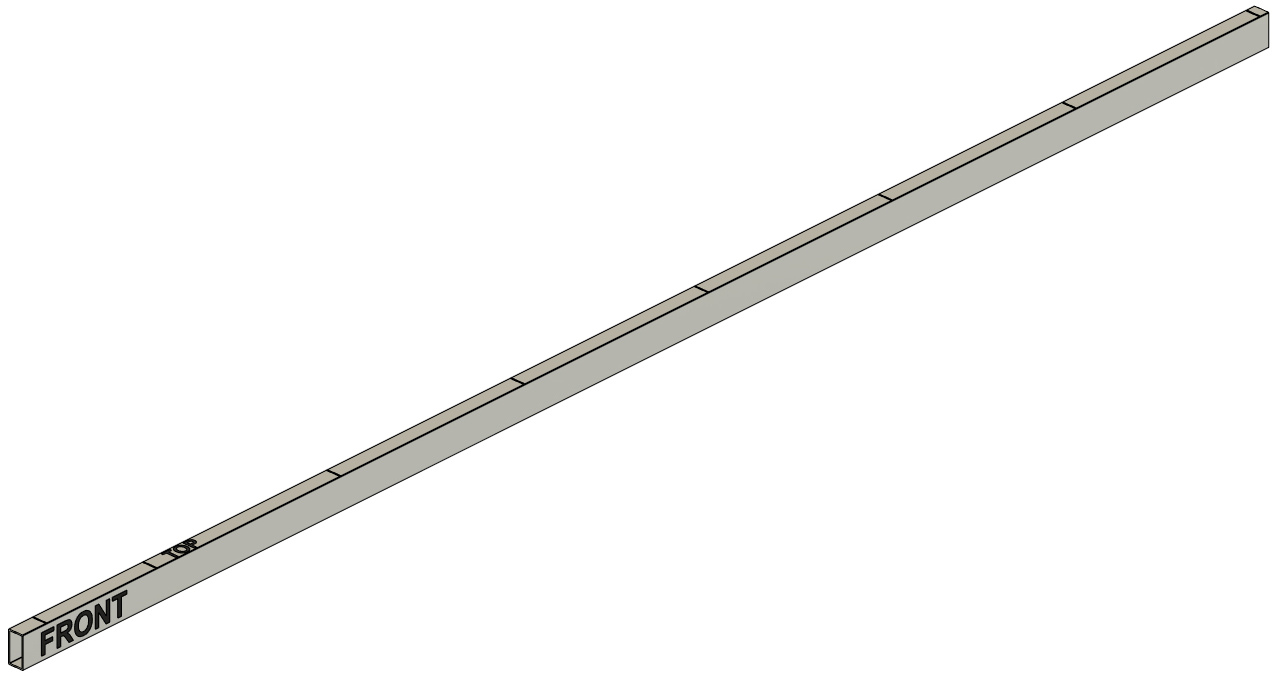
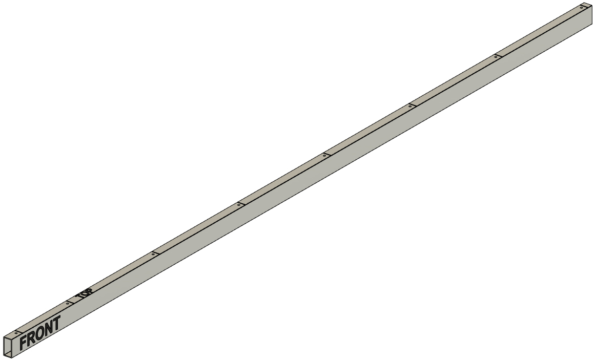
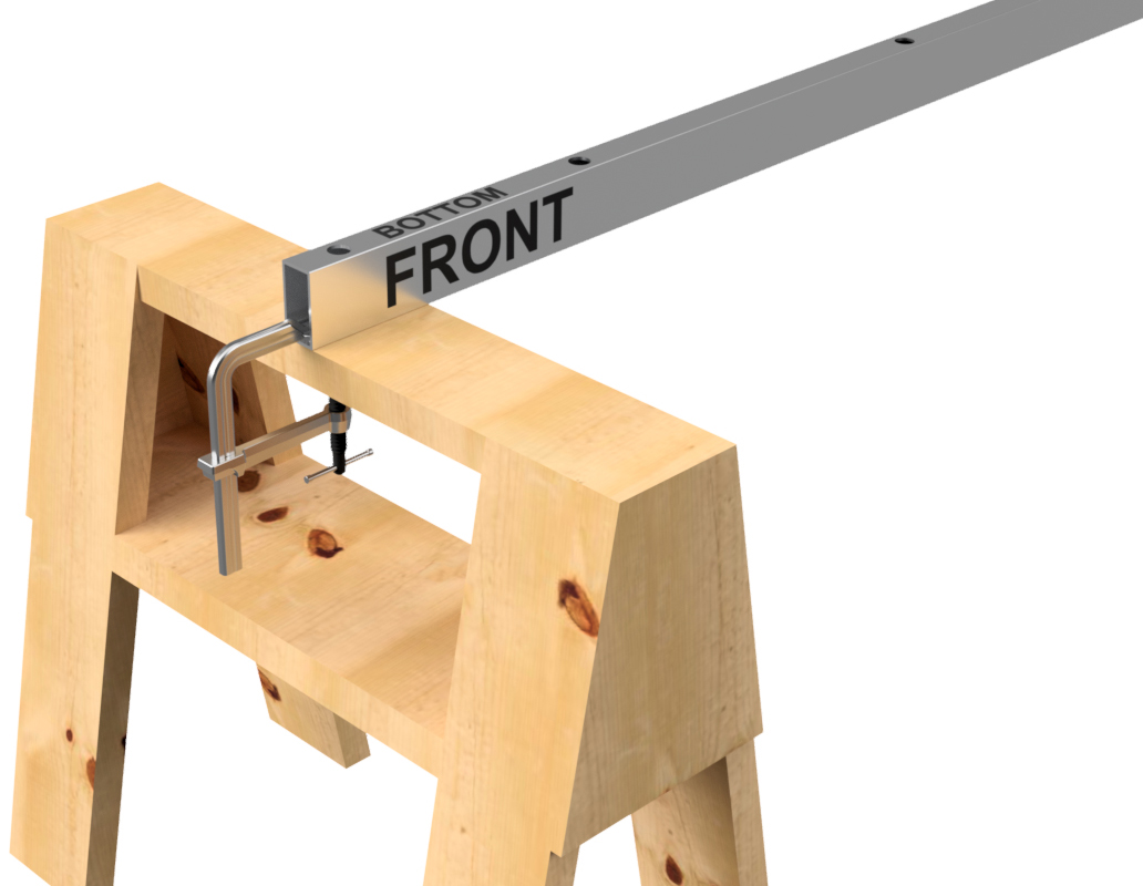
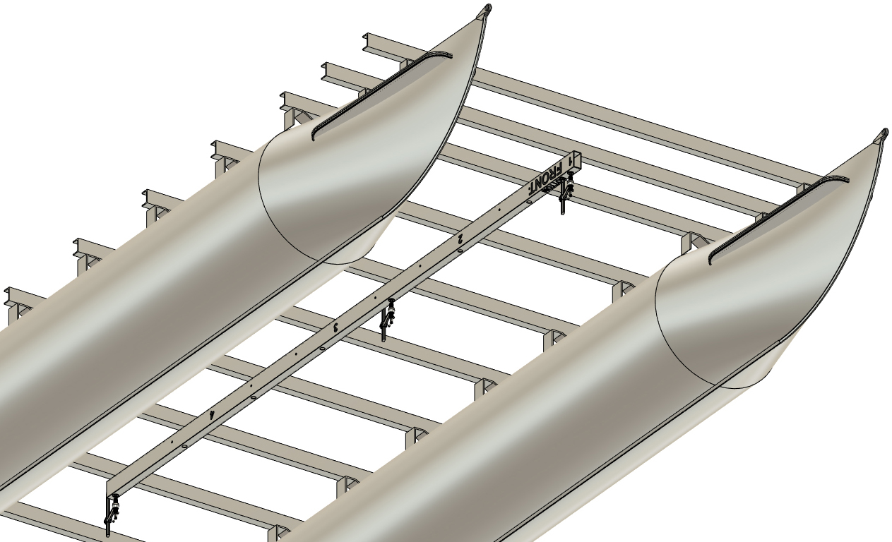
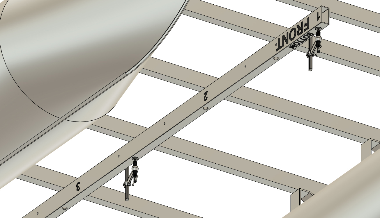
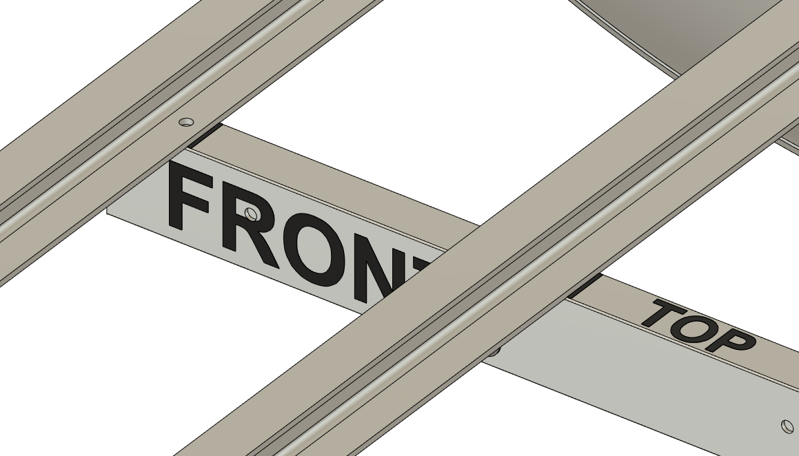
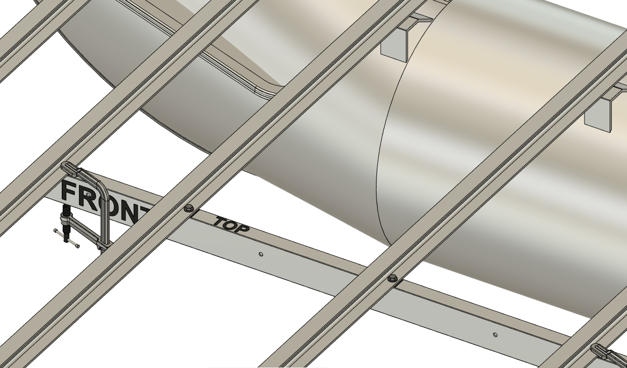
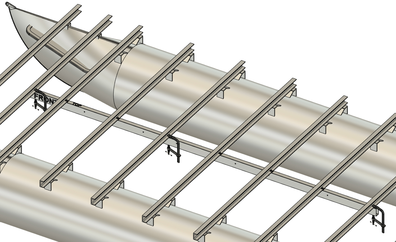
With your 1.5" x 3" mounting tube cut to length, write "TOP", "BOTTOM", and "FRONT" on the tube to ensure that the orientation remains correct for the entirety of the installation process. The 1.5" wide surfaces are the top and bottom of the tube. Write "FRONT" on both sides of the same end of the tube as the other labels. Clamp the tube to the underside of your boat and ensure that the "TOP" label points up. Center it left to right and remember that each end of the tube needs to extend 1" beyond the frontmost and rearmost crossmembers that you're bolting to. We find "F" style clamps easiest to use when clamping under an existing boat.
|

|
|
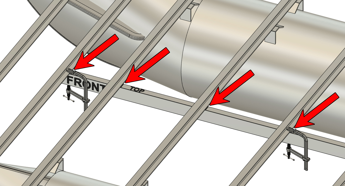
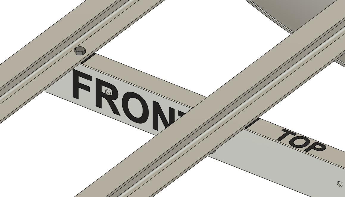
STEP 3
Use a marker to draw lines on the top of the mounting tube where it contacts the crossmembers. Do this from the side of your crossmembers from which you'll have access to the future bolt holes. In our example, we have to draw 8 lines. If your boat has hat channels, you will want to draw a line on both sides of the crossmember. You may have to reposition your clamps to be able to draw all the lines.
Unclamp the mounting tube and remove it from the boat.
|
|
|
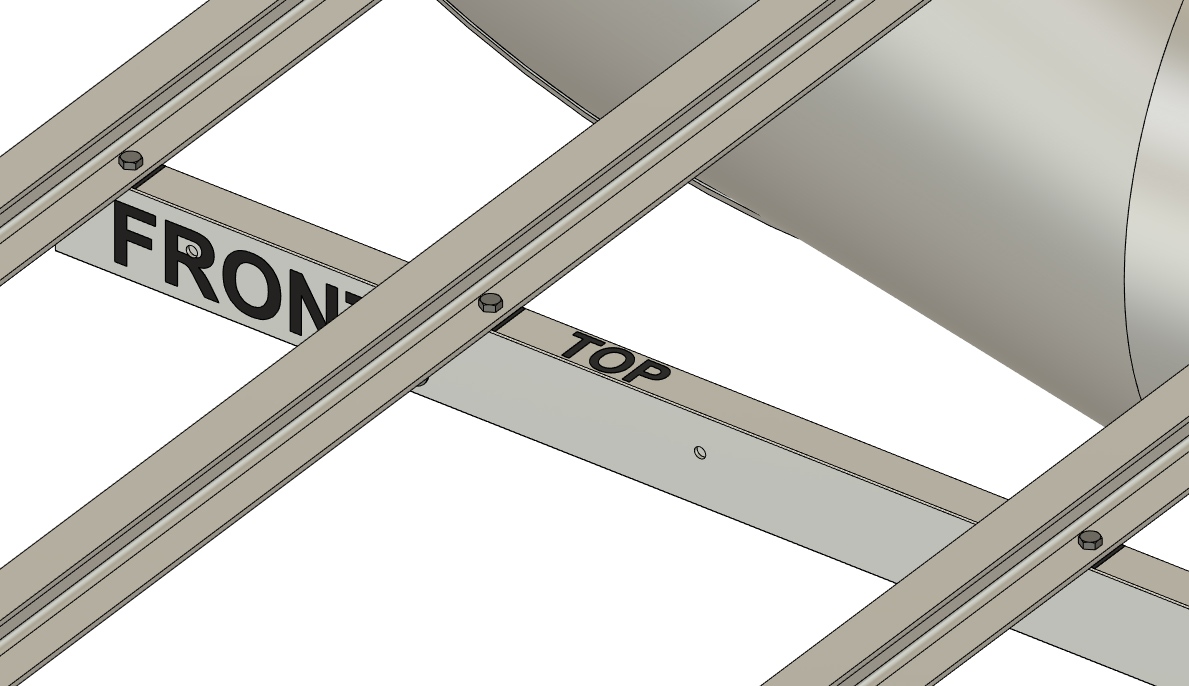
STEP 4
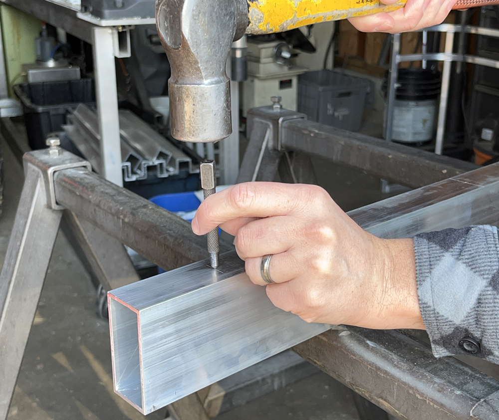
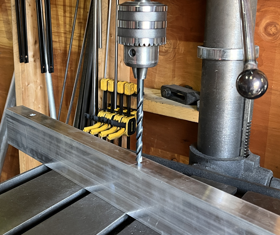
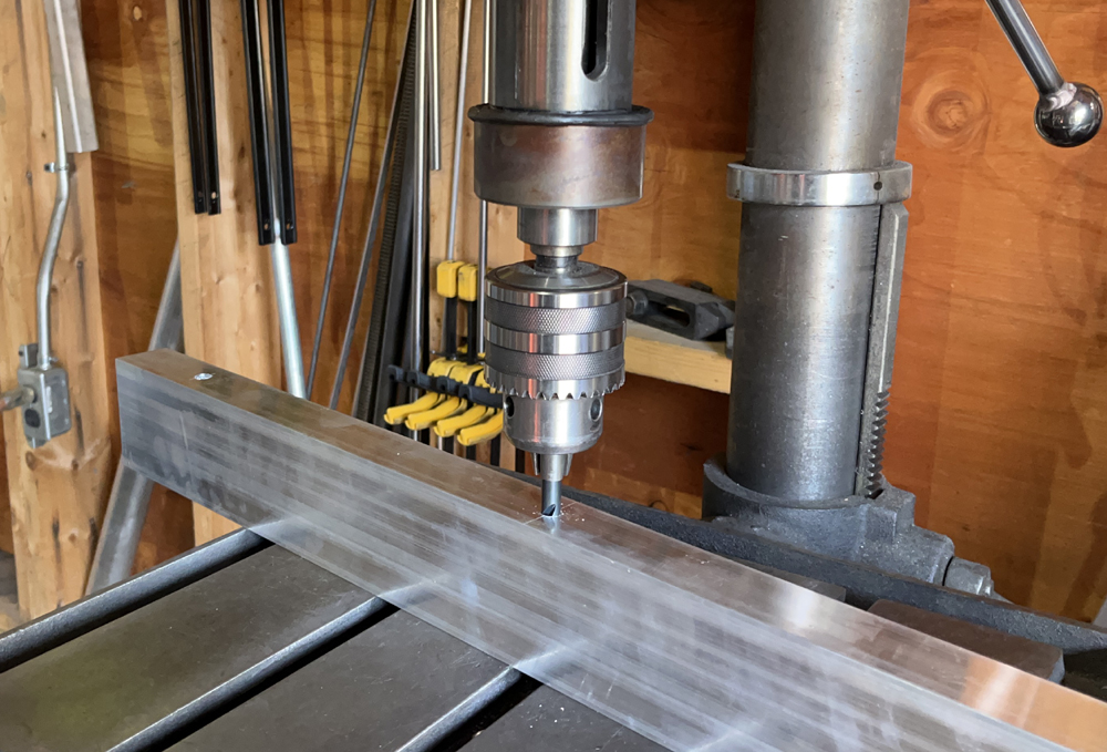
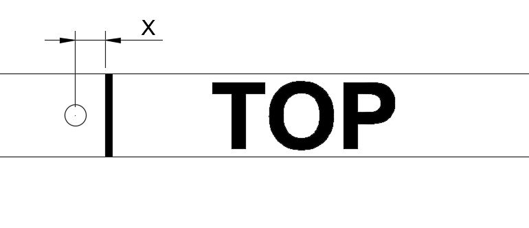
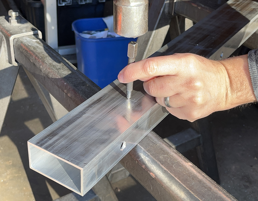
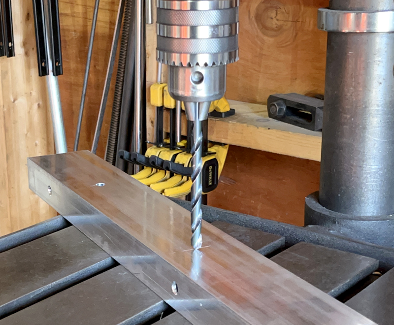
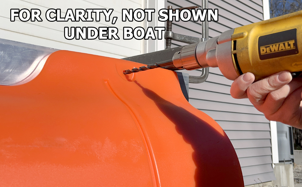
We mentioned prior that you'll need to measure for the center of the flat portion of the lower flange of your crossmembers (edge of flange to center of flat). With that measurement noted, measure the same distance ahead or behind the lines drawn on the top of the tube, depending on the orientation of your crossmembers. Our scenario requires that we measure ahead of the lines to mark the center position of the flat portion of our C-channels. Mark the center of that line (0.75" from the edge of the tube) and use a center punch with a hammer to make a locating divot. Drill through that location and drill all the way through the top and bottom of the tube with a sharp (prohibits wandering) extended length 3/8" drill bit. We strongly recommend using a drill press for this as it's very easy to go askew with a hand drill.
All holes drilled are to be deburred before final assembly. Any 3/8" hole can be deburred using a countersink drill bit, but the larger holes in the next step will need to be deburred with sand paper or alternate deburring tool. We will not stress the importance of deburring again on this page.
 |
|

|
STEP 5
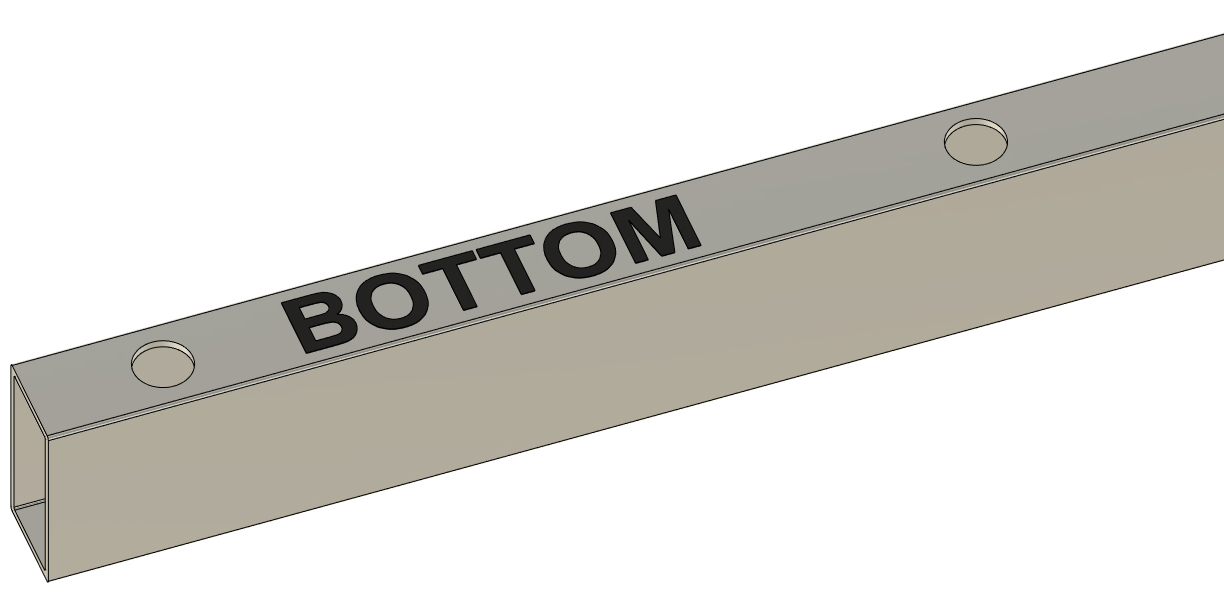
Using a 7/8" step drill bit, drill the 3/8" holes on the bottom of the mounting tube out to 7/8" diameter. This is large enough to fit a 9/16" deep socket through.
|
|

|
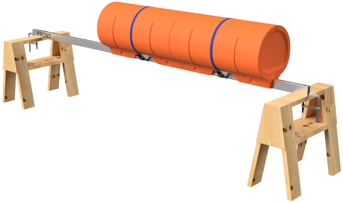
STEP 6
Place the mounting tube across two saw horses so that the face labeled "bottom" faces upward. Clamp the ends of the tube to the saw horses as shown.
|
|
|
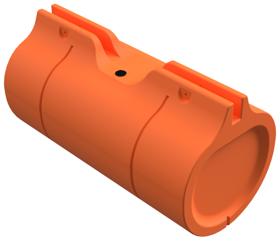
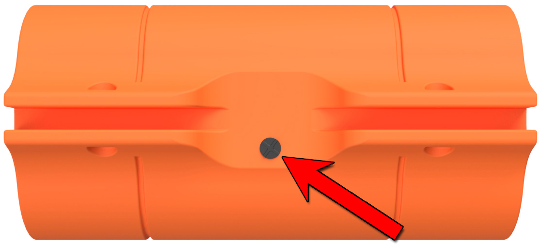
FLOAT ORIENTATION - FOAM FILLING PLUGS
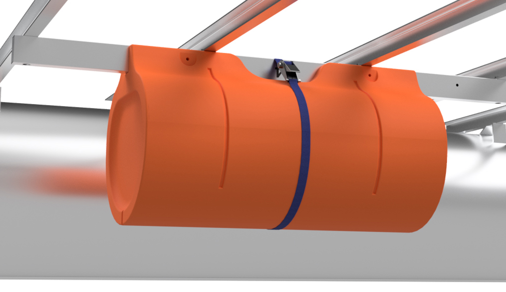
Each of the straight floats (blunt end floats) in your boat kit have a foam filling plug on the upper flat portion. This plug is offset to ensure that the frame seats properly in the float. For this type of installation, it doesn't matter what side of the tube the plugs go on, but we like to put all the plugs on the same side for the sake of consistency.
|
|
|
STEP 7
If you are building a dual-nose (nose cone on both ends) pontoon assembly, please read the note in the section below before moving forward.
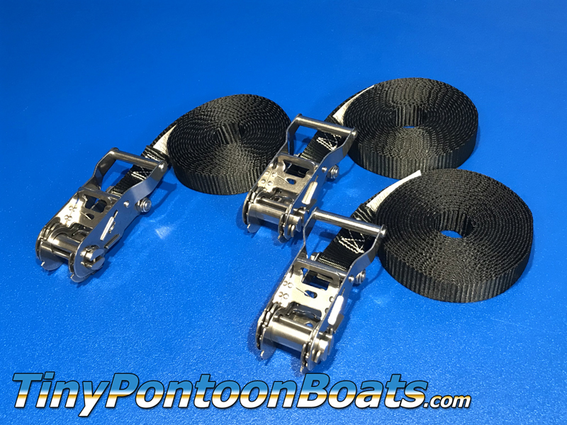
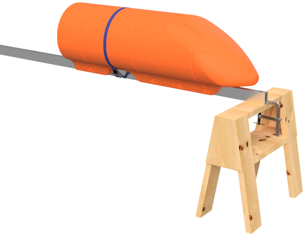
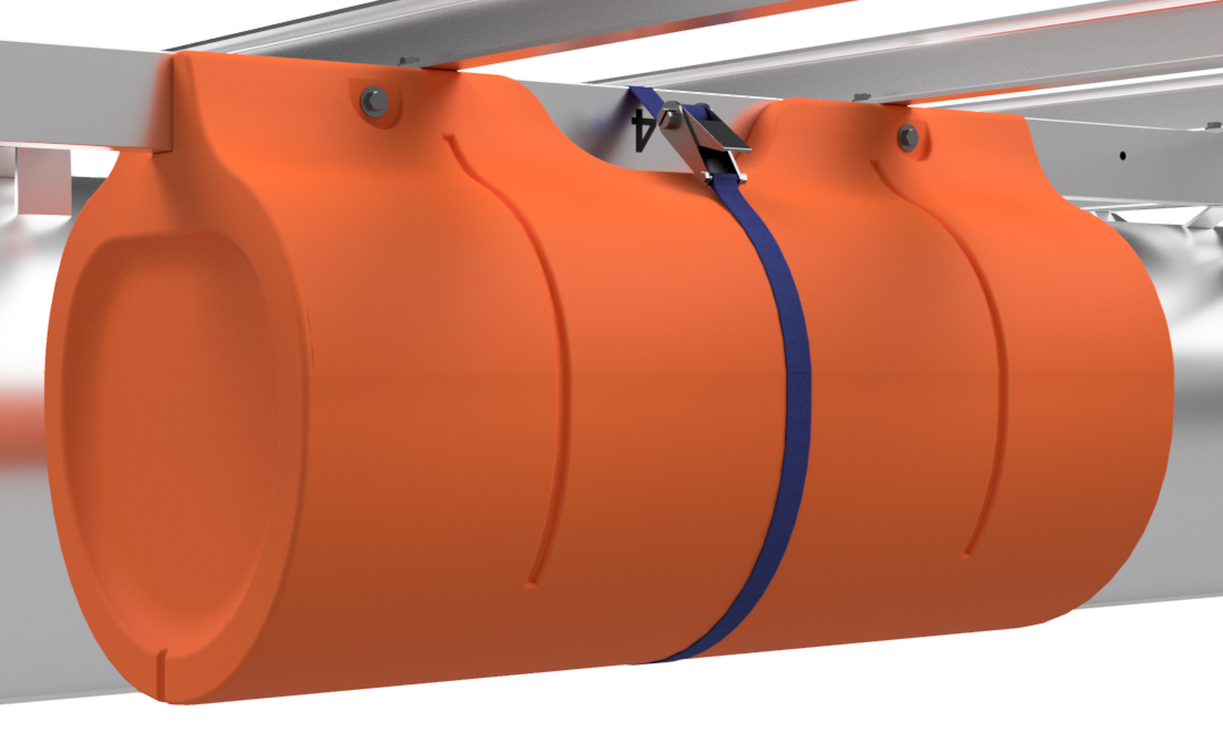
Place one of the straight floats (blunt end floats) on the rear end (opposite of "FRONT" labeled end) of the mounting tube. If you had to add length to the rear end (nearest the stern of your boat) of the mounting tube in step 1, the float is to be placed that distance away from the end of the tube. With the 8'x18' boat that we're showing in these instructions, we had to extend the rear end of the tube by 12.5", so the end of the float is placed 12.5" from the rear end of the mounting tube. With the float's position adjusted (can use a plastic or rubber mallet to tap the float into position) place a ratchet strap around it to hold it firmly in position.
|

|
|
NOTE FOR DUAL-NOSE PONTOON ASSEMBLIES
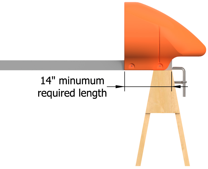
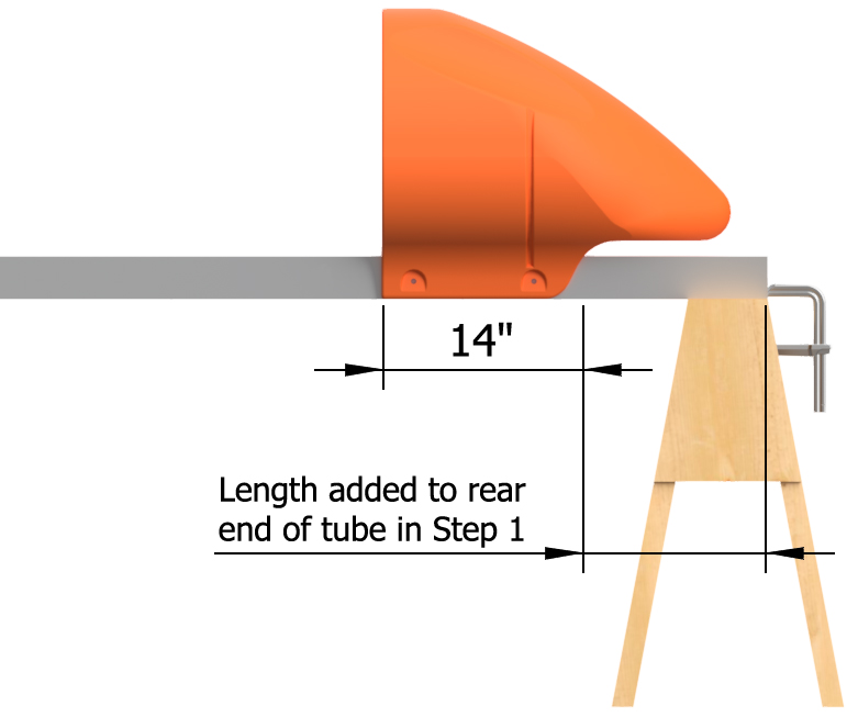
If you purchased a set of floats with 2 nose cones (nose cones for both ends), your approach will be a bit different. With our typical dual-nose arrangement for 18" floats, each nose cone requires 14" of mounting tube. That means that the flat end of the nose cone is placed 14" in from the end of the minimum length mounting tube. If your arrangement of floats has a nose cone pointing toward the stern of your boat (common when placing a pontoon assembly close to the transom), the length added to the rear of the mounting tube in step 1 must be taken into account. For instance, if your tube required an additional 6" in step 1, the flat portion of the nose cone must land 20" from the rear end of the tube. We have provided diagrams showing what we mean. Depending on your placement requirements, you may also choose to just center the set of floats on the mounting tube for simplicity.
With a nose cone in place, position a straight float on the tube against the nose cone and adjust as necessary. Place a ratchet strap around the straight float. You will not be able to place a ratchet strap around the nose cone.
|
|
|
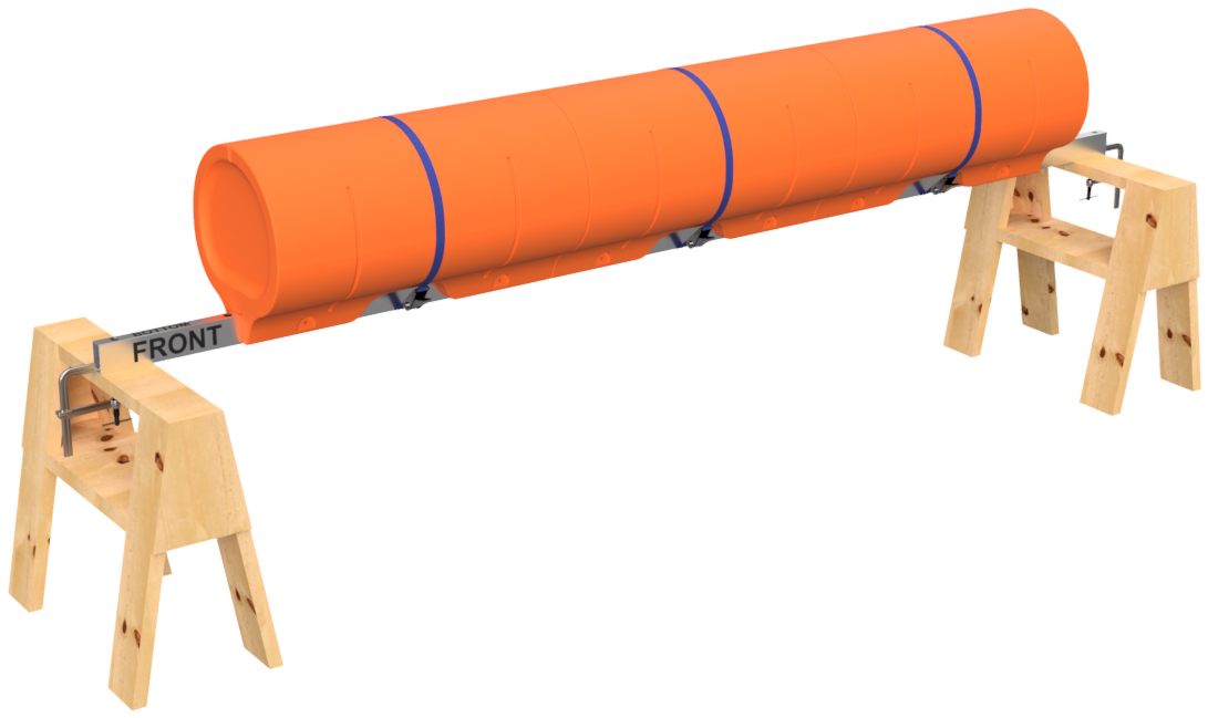
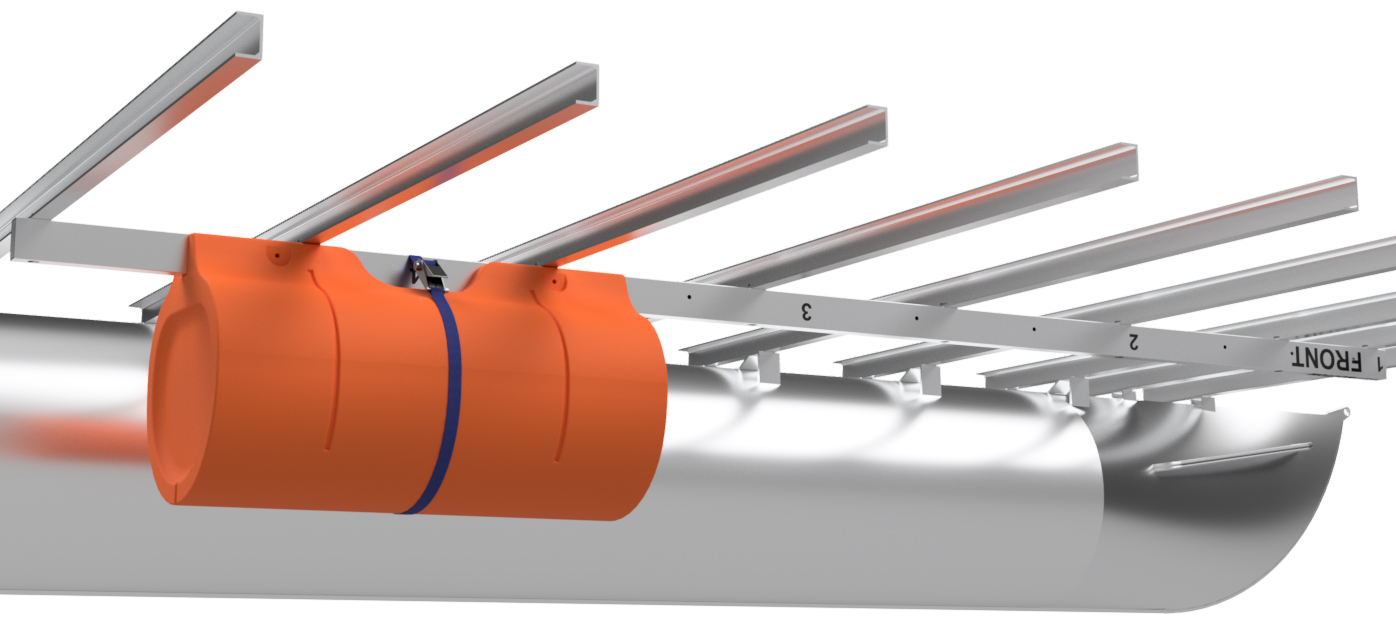
STEP 8
Place the remaining straight floats onto the mounting tube and install ratchet straps around them to hold their positions. When placing the floats on the mounting tube, tap them securely against the previously installed float. Verify the floats' overall positions and adjust as necessary.
|
|
|
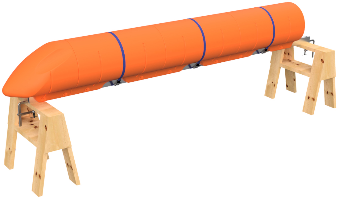
STEP 9
Place a nose cone float on the front of the pontoon assembly as shown. Due to the shape of the nose cone, you will not be able to place a ratchet strap over it.
|
|
|
STEP 10
Using a 3/8" transfer punch, go down BOTH sides of the pontoon assembly to mark the position of each bolt hole. To do this, insert the punch into EVERY bolt hole and give it a solid tap with your hammer. Don't smash it; just give it a solid tap. The ratchet straps will hold the straight floats in position for this, but nose cones will have to be held in position by hand when you do this.
|
|
|
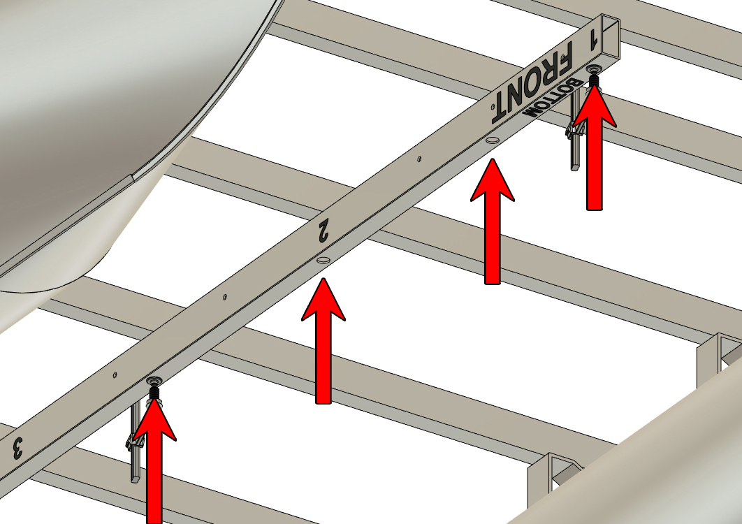
STEP 11
Remove the ratchet straps. Before removing the floats, use a marker to number the positions of the floats on the mounting tube as shown. Remove the floats and unclamp the mounting tube from the saw horses.
|

|
STEP 12
Using a standard center punch, make the marks you made with the transfer punch in step 10 more pronounce. This will make the holes easier to drill in the next step.
|
|
|
STEP 13
Using a SHARP (prohibits wandering of the bit) 3/8" diameter drill bit (length of bit does not matter), drill through ONE WALL of the mounting tube at each marked position. DO NOT drill all the way through both sides of the tube during this operation. Drill through every marked position on one side of the part, flip it, and drill through every marked position on the other side of the part.
For this operation, you can use a hand-held drill, but we find it much easier and quicker to use a drill press. If using a hand-held drill, be careful to keep the drill bit perpendicular to the surface you are drilling through. You can't undrill holes, so take your time. Remember to debur your holes.
|
|
|
STEP 14
Clamp the mounting tube back under your boat and make sure that the "FRONT" label is closest to your boat's bow and that the "BOTTOM" label faces down. Center the tube left to right and double-check all your tube placement measurements. Double-check that the tube extends 1" beyond the frontmost and rearmost crossmembers you will be bolting to.
The tube placement will determine the location of the holes you drill next and you can't undrill those holes. If your mounting tube is not placed properly, you will cause permanent damage to your boat in the next step.
|
|
|
STEP 15
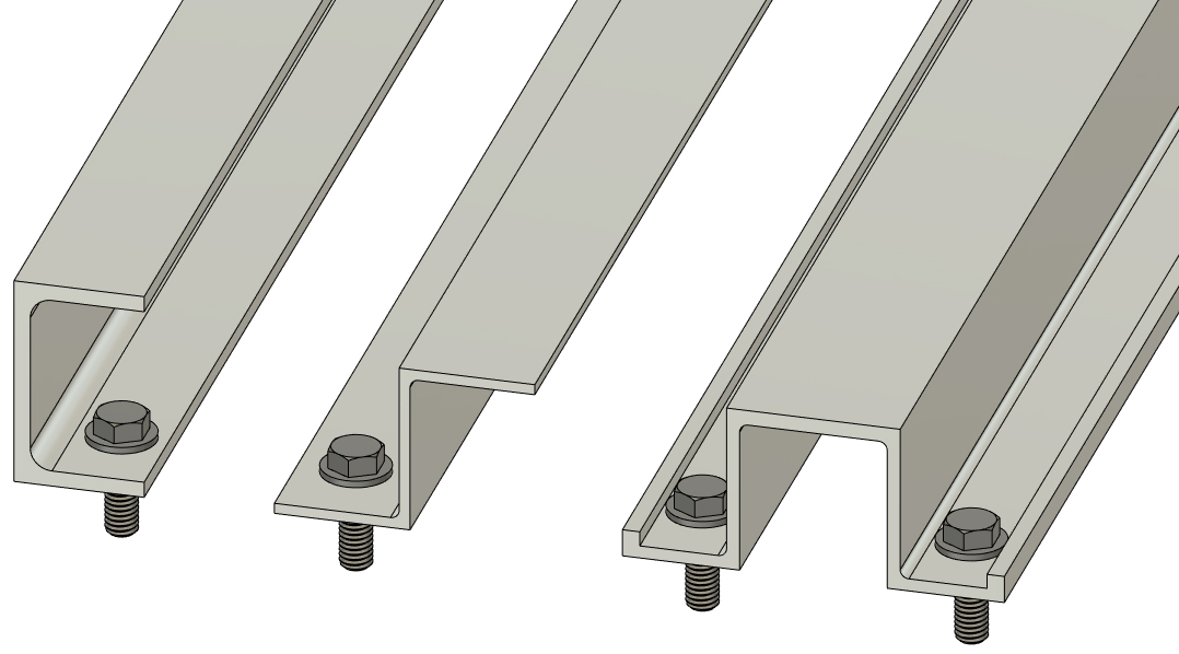
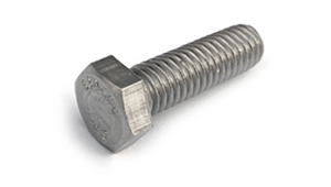
With the mounting tube clamped into position, mount your extended-length 3/8" drill bit in your hand drill. Insert the drill bit through each 7/8" hole and drill upward through the 3/8" holes in the top of the mounting tube. Drill through the bottom flange of each crossmember you'll be bolting to. After drilling each hole, place a 3/8" x 1 1/4" hex bolt into the hole from the top of the flange. This will cause the holes to stay aligned as you continue. Do this for every vertical hole in the mounting tube. You may have to reposition your clamps to be able to reach every hole. For the 8'x18' boat we're working on here, we have to drill through 8 crossmembers.
|

|
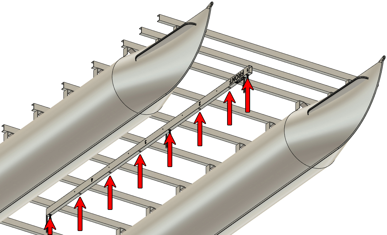
|
STEP 16
Remove the clamps and the mounting tube from the boat's frame. Debur the holes you just drilled in your crossmembers. The bottom of the crossmember holes is most important to debur to ensure a flat mounting surface.
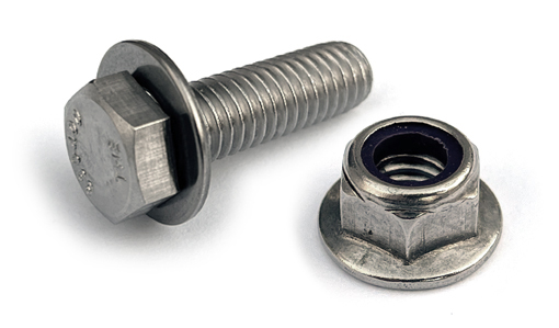
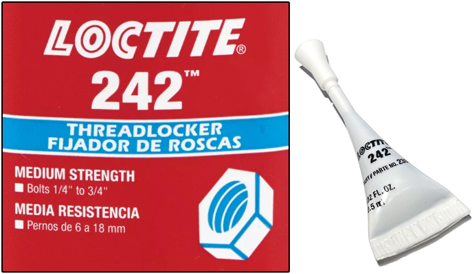
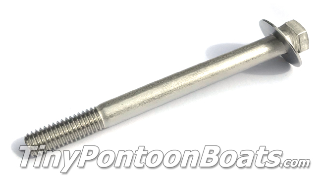
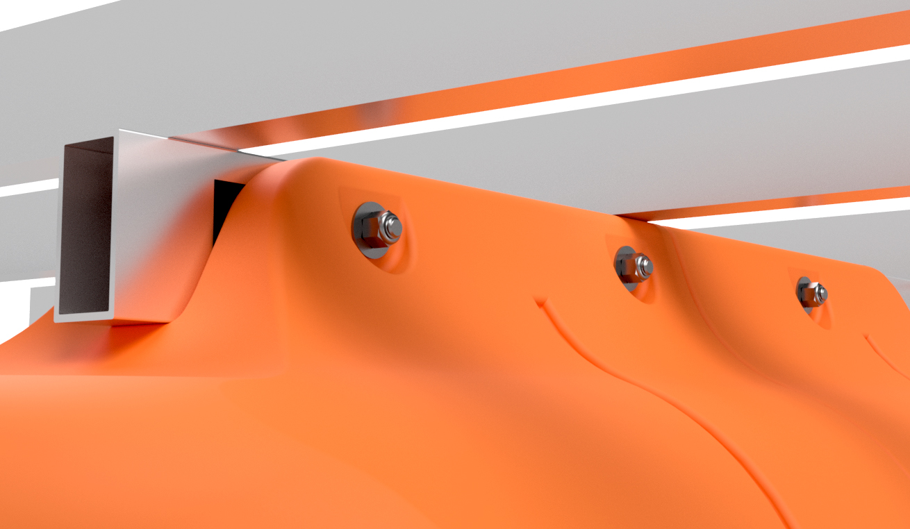
Clamp the mounting tube back under the boat and align the bolt holes. Insert a 3/8" x 1 1/4" hex bolt with a 3/8" SAE flat washer into each hole from the top of your crossmember's lower flange. Do this for each hole you can reach without removing clamps. Apply blue LocTite (type 242 - see note below) to a 3/8" flange nut and insert it into the large holes in the bottom of the mounting tube with a 3/8" drive ratchet with an extension and 9/16" deep-well socket. You will require a 9/16" box wrench to hold the bolt. If using a torque wrench, 55 foot pounds is maximum torque for these nuts and bolts. Remove the clamps and install the same hardware into any crossmember bolt hole that was blocked by a clamp. Double-check that your mounting tube has been bolted to each crossmember it contacts. NOTE: The LocTite lubricates the threads, makes the nuts more secure, and is 100% required. DO NOT SKIP THIS STEP as stainless steel threads have a tendency to jam without lubrication.
  |
|
|
STEP 17
The remainder of the assembly process will be mounting the floats themselves to the affixed mounting tube. The remaining portion of the installation is a 2-person task and is VERY difficult to do without a helper. Get a 6-pack, order a pizza, and call a buddy to help with the remainder of your installation.
From here forward, you will need to match up the numbers you wrote on the mounting tube and floats in step 11. Install the straight float that matches up with the rearmost position on your mounting tube. For our assembly, it's float position 4. Use a ratchet strap to hold the float onto the mounting tube and line up the bolt holes in the float and mounting tube. Due to low clearance, you may have to contort or use a mirror to do this.
|
|
|
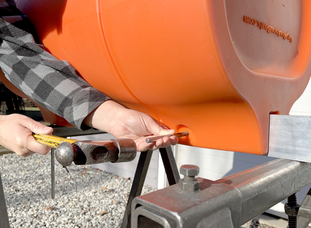
STEP 18
With a 3/8" drill bit mounted in your hand-held drill, start at the rearmost bolt hole of the float and drill through the bolt hole in the float and all the way through both sides of the mounting tube. When doing this, go slowly, as your drill bit should only be clearing chips and verifying hole alignment, not drilling a new hole. Insert one of the 3/8" x 4 1/2" hex bolts with a 1" outside diameter fender washer, and tap it through the hole with a hammer. We prefer to use a plastic hammer for this. Drill through the next hole forward and insert a bolt with fender washer. DO NOT INSTALL THE NUTS YET.
Remove the ratchet strap from the float.
|

|
|
STEP 19
Repeat step 17 and 18 with the next float forward, one float at a time, until all your straight floats are hanging from the mounting tube. DO NOT INSTALL THE NUTS YET.
|

|

|
STEP 20
Slide the nose cone onto the mounting tube. As your helper holds it against the bottom of the tube, align the float's holes with the holes drilled in the tube. Use your drill in the same way as in step 18 and 19, then tap a bolt with washer into each hole. If installing a dual-nose pontoon assembly, do the same with the rear-facing nose cone. DO NOT INSTALL THE NUTS YET
|
|
|
STEP 21
With bolts through every float mounting hole, use a rag to remove any chips from the exposed threads of the bolts you just inserted. Place a 1" diameter fender washer over each of the bolts. DO NOT INSTALL THE NUTS YET. Apply blue LocTite (type 242) to the exposed threads of each float bolt. Once again, the LocTite lubricates the threads, makes the nuts more secure, and is 100% required. DO NOT SKIP THIS STEP.
Thread 3/8" lock nuts onto each of the bolts and tighten the nuts until the mounting flanges on the floats start to flex inward. We do not have a torque specification beyond this. 
|
|
|
YOUR INSTALLATION IS COMPLETE!
The installation of your third pontoon is now complete! If you choose to remove the marker from the mounting tube and floats, a little bit of lacquer thinner and a rag will do the job and not hurt either. Also, if you want to plug the ends of the mounting tube, McMaster sells a plastic plug that pops right in. A link the plug is listed below.
Enjoy your additional buoyancy and have fun on the water! |