
|
603-630-5658
|
|
tinypontoonboats@gmail.com
|

|
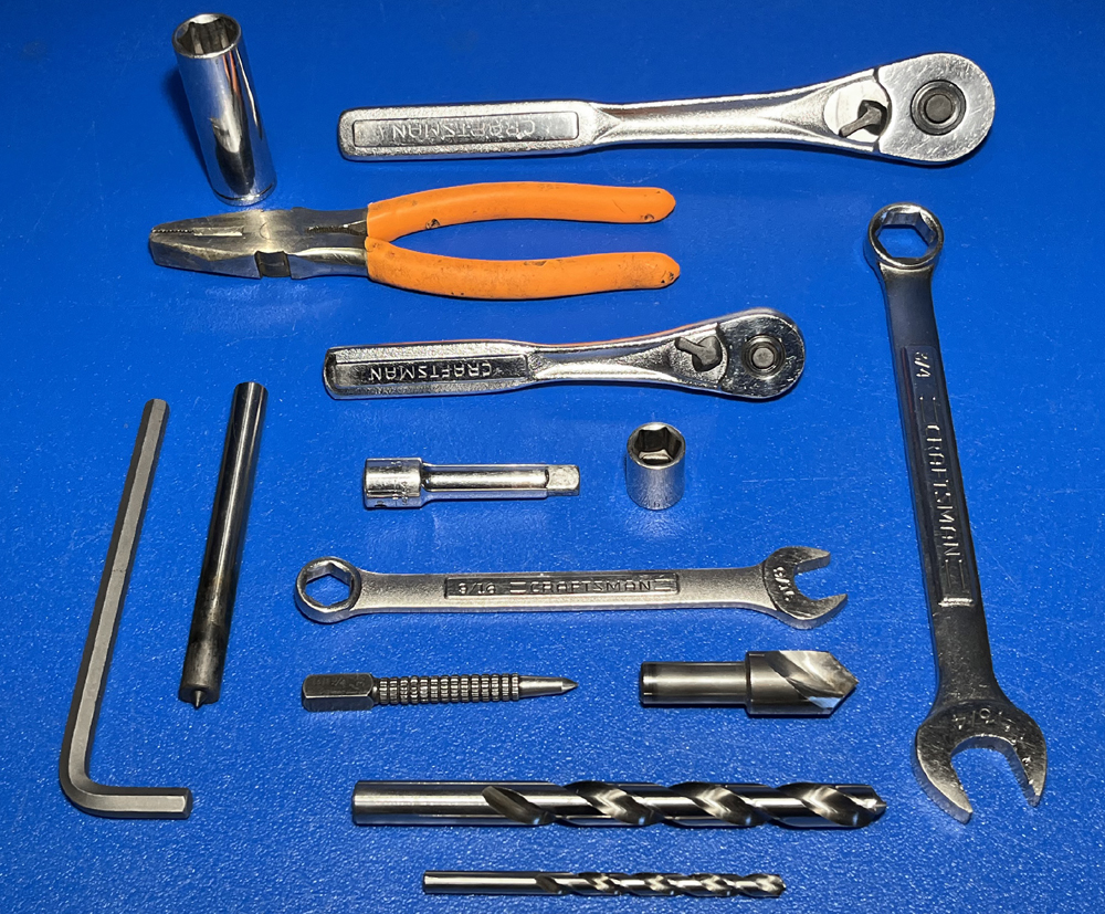
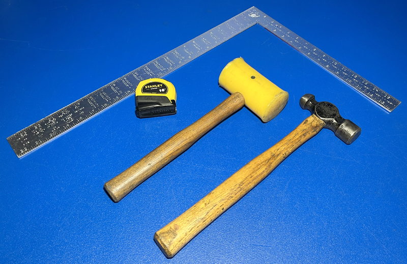
REQUIRED TOOLS
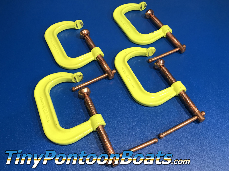
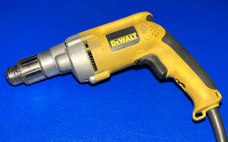
The frame and pontoon assembly for our single nose pontoon boats with 27" floats requires a few basic tools, as well as a couple specialized tools. Below we have provided a list of everything that you'll need, as well as part numbers and links to where you can get the specialized tools from McMaster, which is a reasonably priced industrial supplier. Click on the part number to view the item on the McMaster website. Many customers will already have the majority of these tools, if not all of them. These tools (other than perhaps the transfer punch) should be stocked at your local home supply or hardware store as well.
|
|

|
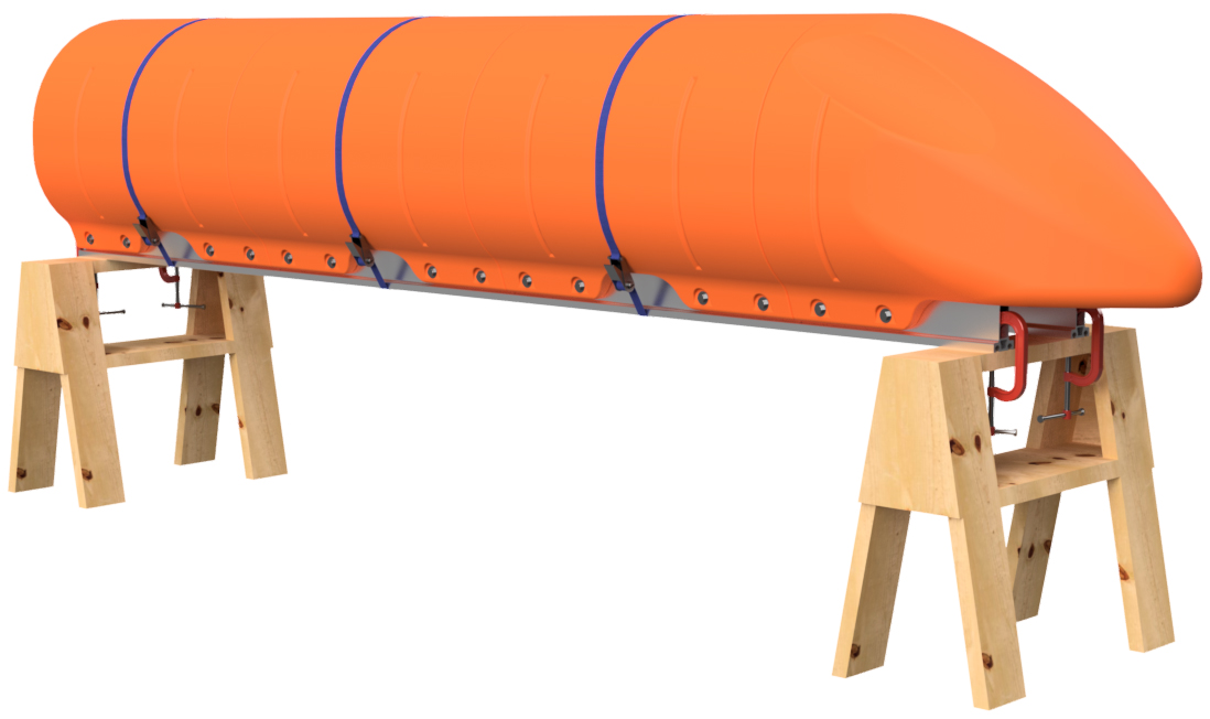
STEP 1
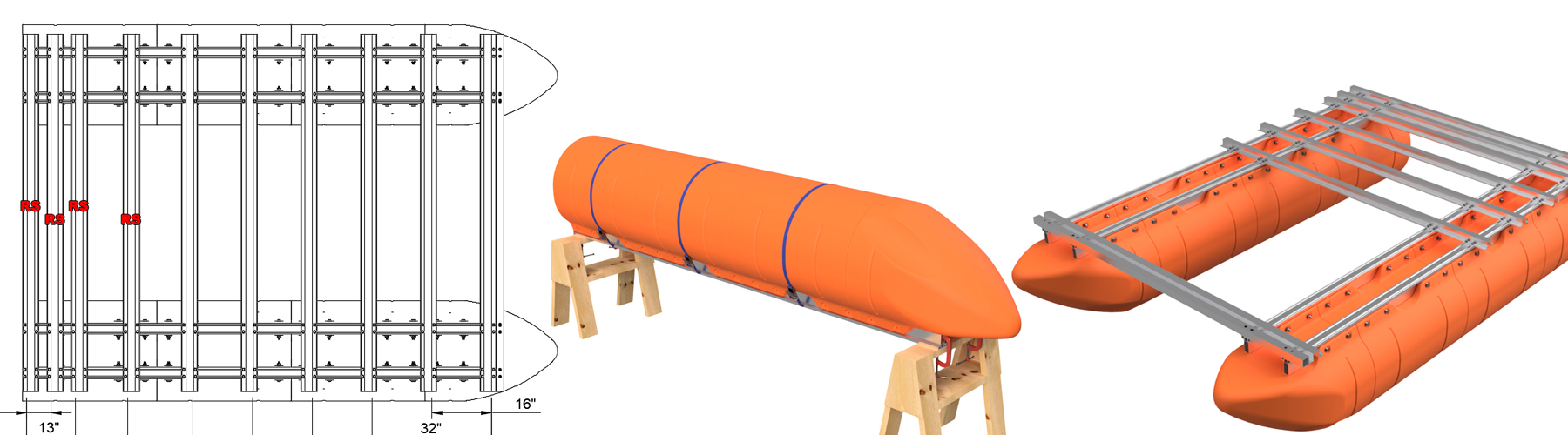
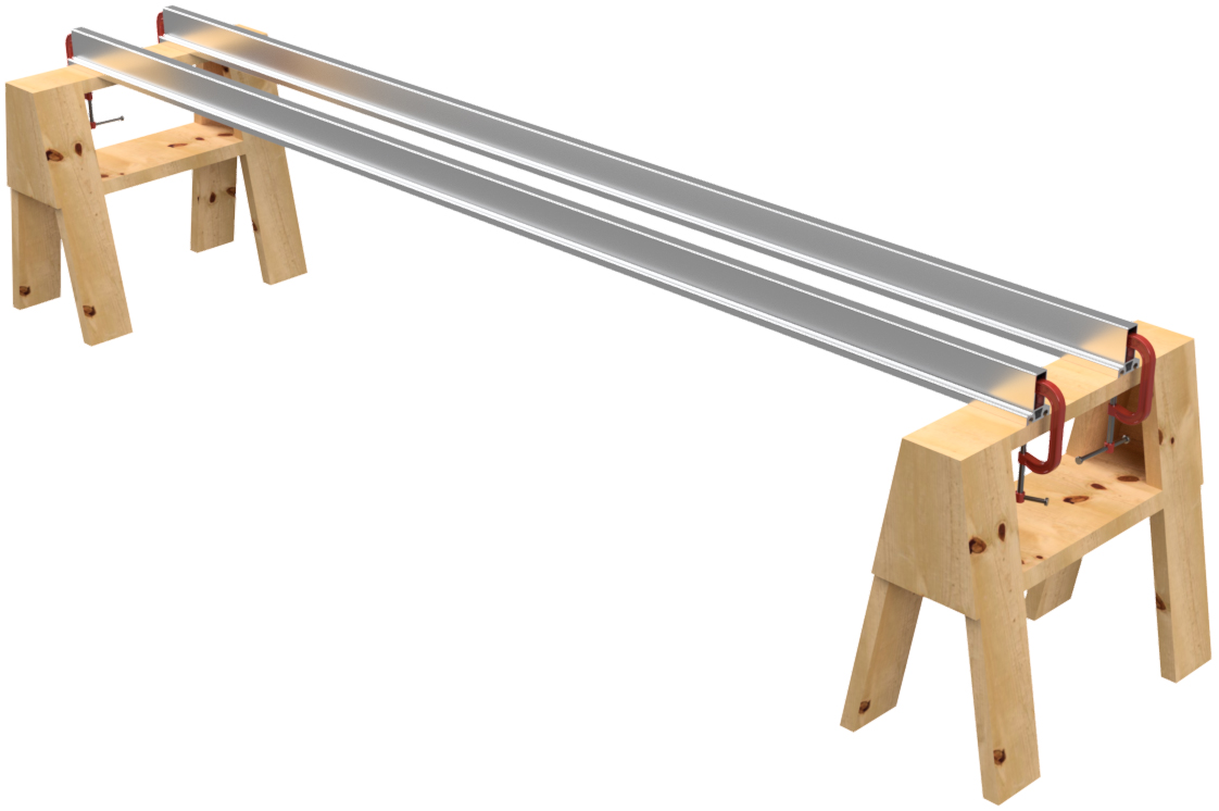
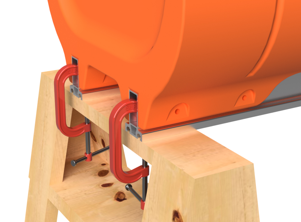
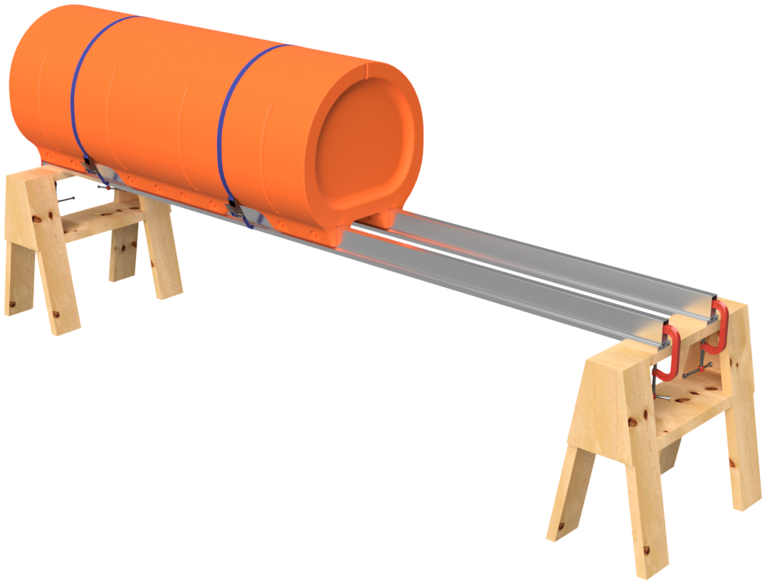
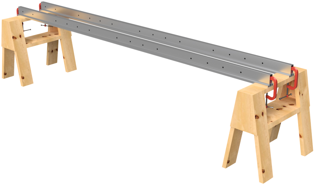
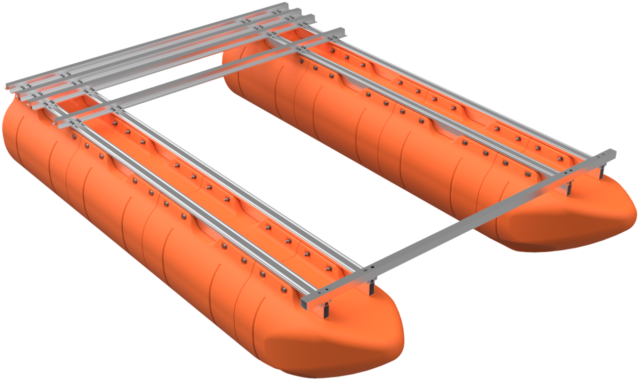
Place two of the pontoon main beam extrusions across two saw horses. The main beams are the aluminum tubes that have a "T" shaped cross section with two slots on the top. Position the main beams so that the slots face down and are about 12" on center. Use a square to ensure that the ends are even. Clamp the two frame members to your saw horses.
|
|
|
STEP 2
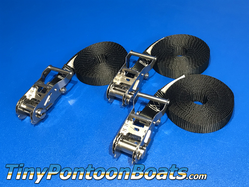
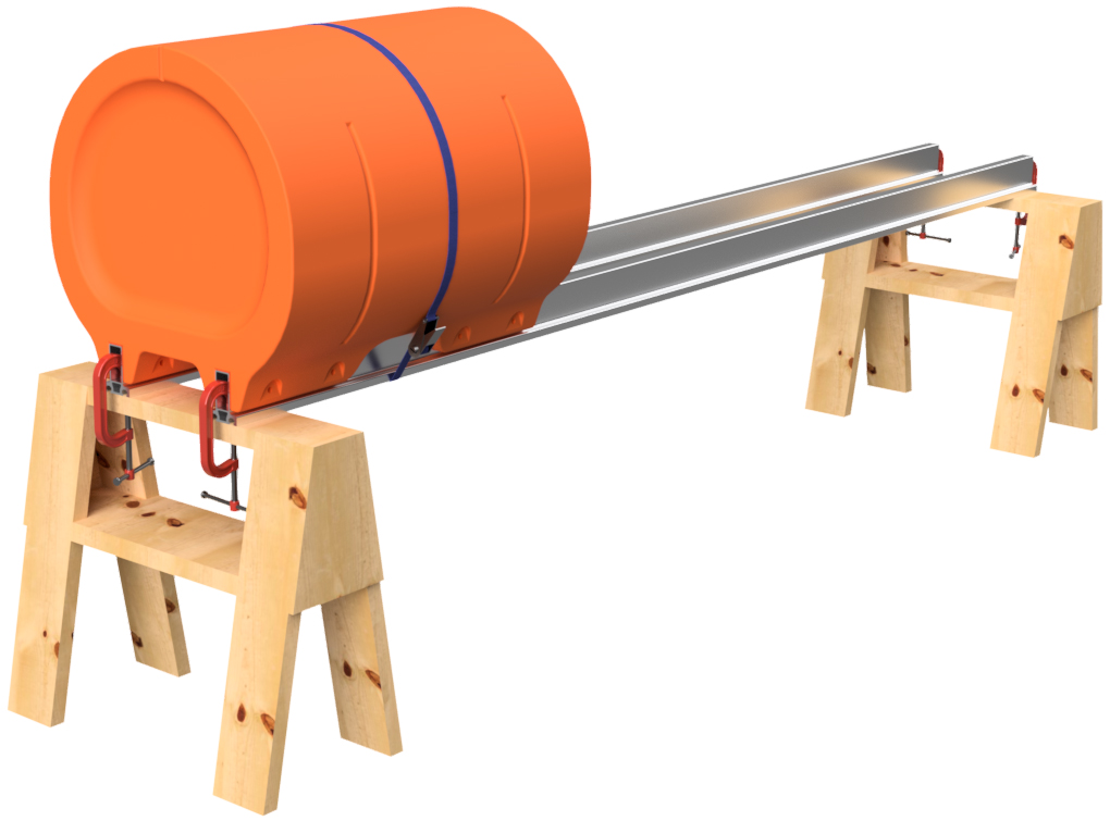
Place one of the straight floats (blunt end floats) on an end of the main beams. You may have to adjust the spacing of your main beams. Tap the float into position so that the end of the float is even with the end of the main beams. A rubber or plastic hammer can be used for this. Place a ratchet strap around the float and the main beams to temporarily hold it in position and ensure that the float is properly seated on the frame members.
NOTE:
|
|
|
STEP 3
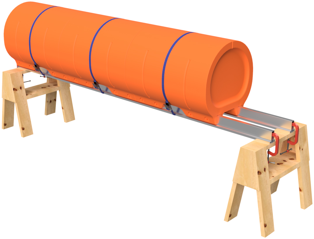
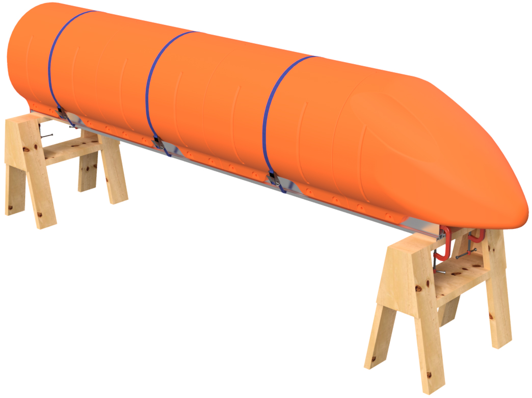
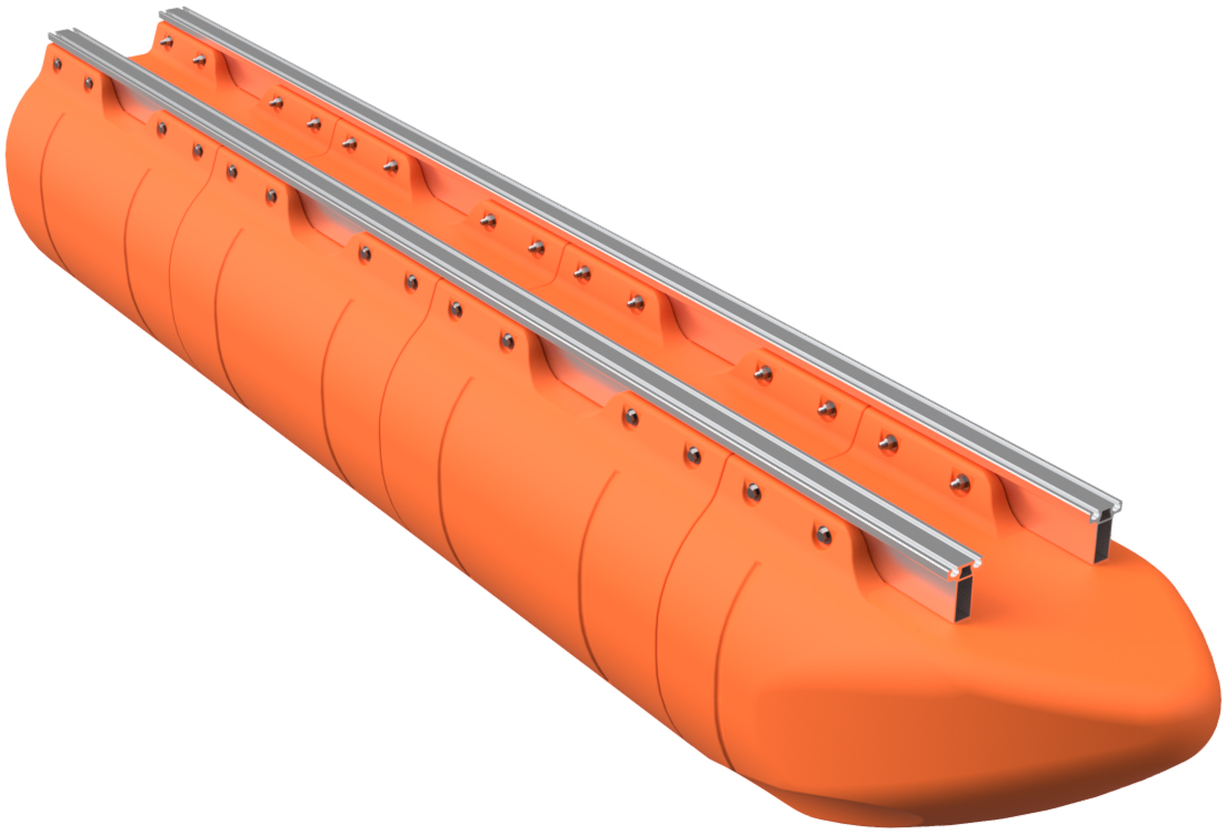
Place the remaining straight floats for the pontoon assembly onto the main beams and install ratchet straps around each float. 9' long boats require 2 straight floats per pontoon, 12' boats require 3, and 15' boats require 4 straight floats per pontoon assembly. When placing the floats on the main beams, tap them securely against the previously installed float. Verify that the first float is still even with the end of the main beams and adjust as necessary. Verify that your straps are secured.
|
|
|
STEP 4
Place a nose cone float on the front of the pontoon assembly as shown. Due to the shape of the nose cone, you will not be able to place a ratchet strap over it.
|
|
|
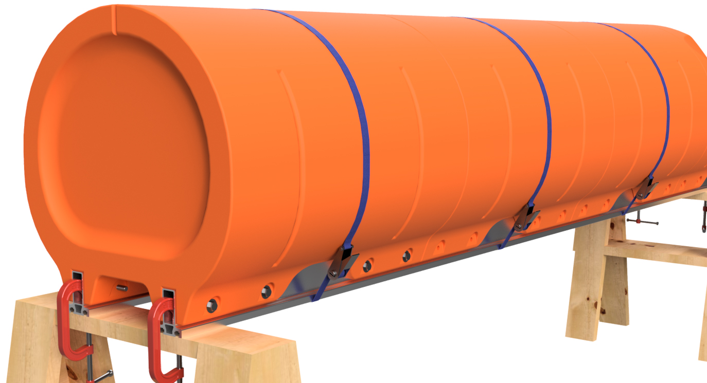
STEP 5
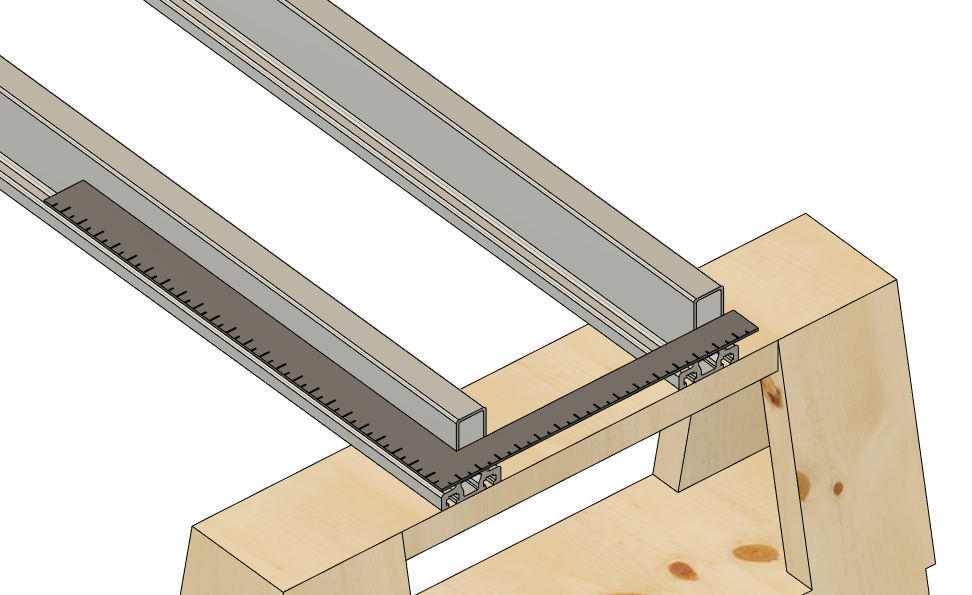
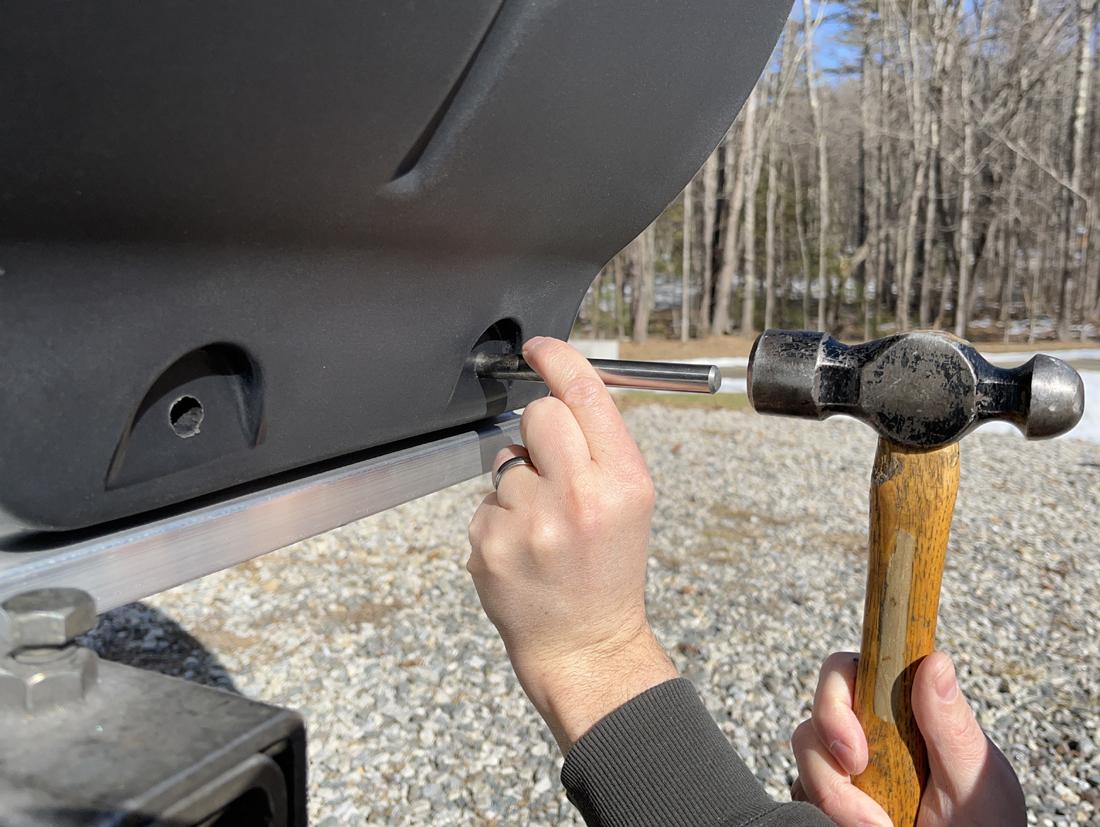
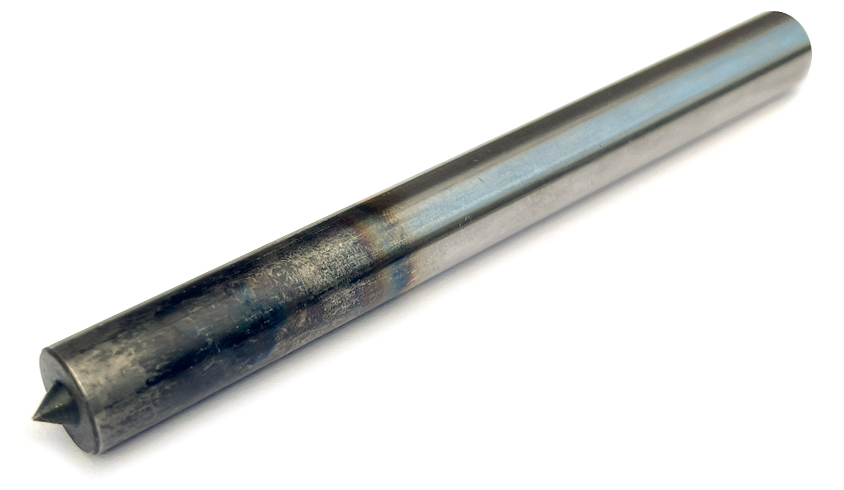
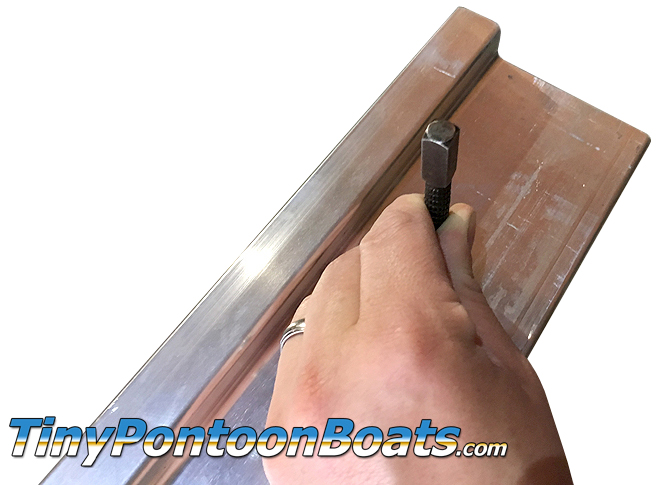
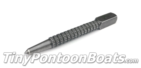
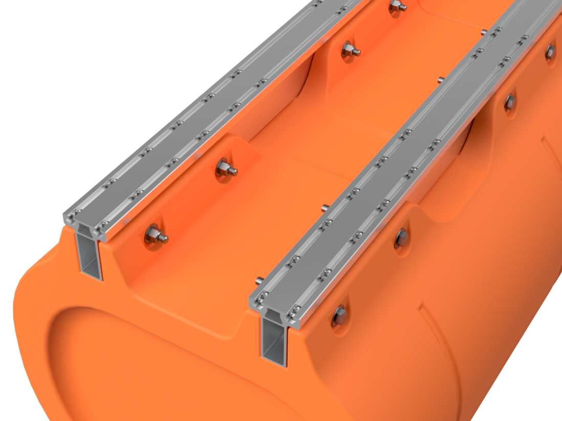
Using a 1/2" transfer punch, go down both sides of both sets of mounting channels on the plastic floats and use the punch with a hammer to mark EVERY bolt hole position through the molded-in bolt holes in the floats. Don't smash it; just give the punch a solid tap. You will have to do this from both the outside set of holes and the inside set of holes. This means that you'll have to go under the pontoon assembly on your saw horses to mark the inner holes. It's inconvenient, but 100% necessary.
|
|
|
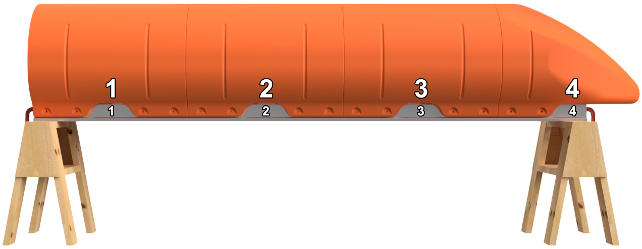
STEP 6
Remove the ratchet straps. Before removing the floats, number the positions of the floats on the main beams as shown. Number the floats and main beams on both sides of the pontoon assembly. For instance, if you're building a 12' long pontoon, you'll want to label position 1, 2, 3, and 4 on one side and 5,6,7, and 8 on the other. This ensures that you don't mix up the positions of the floats after you drill holes. You can use a piece of masking tape to write on or you can use a marker to write on the floats and main beams. If using a marker, lacquer paint thinner will remove the ink after assembly, and the paint thinner will not hurt the plastic or the aluminum. Remove the floats and unclamp the main beams from the saw horses.
|
|
STEP 7
Using a standard center punch, make the marks you made with the transfer punch in step 5 more pronounce. This will make the holes easier to drill in the next step.
|
|
|
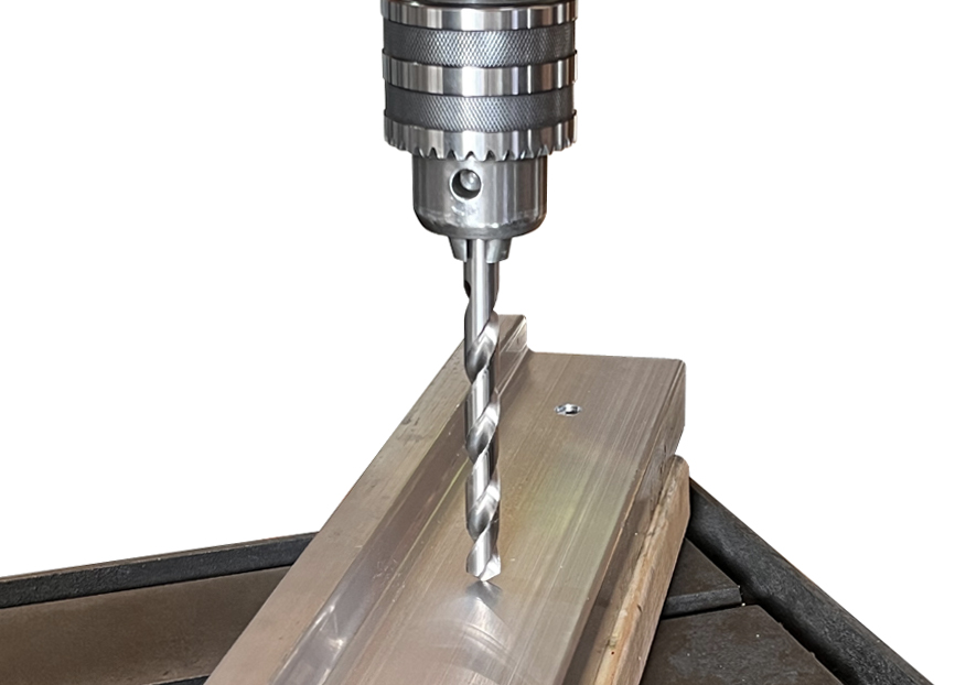
STEP 8
Using a SHARP (prohibits wandering of the bit) 1/4" diameter drill bit, drill through ONE WALL of each main beam at each marked position. DO NOT drill all the way through both sides of the main beams during this operation. Drill through every marked position on one side of each part, flip it, and drill through every marked position on the other side. After drilling all the 1/4" holes in both main beams, use a 1/2" diameter drill bit to drill through every 1/4" hole. Once again, only drill through one wall at a time for each hole position.
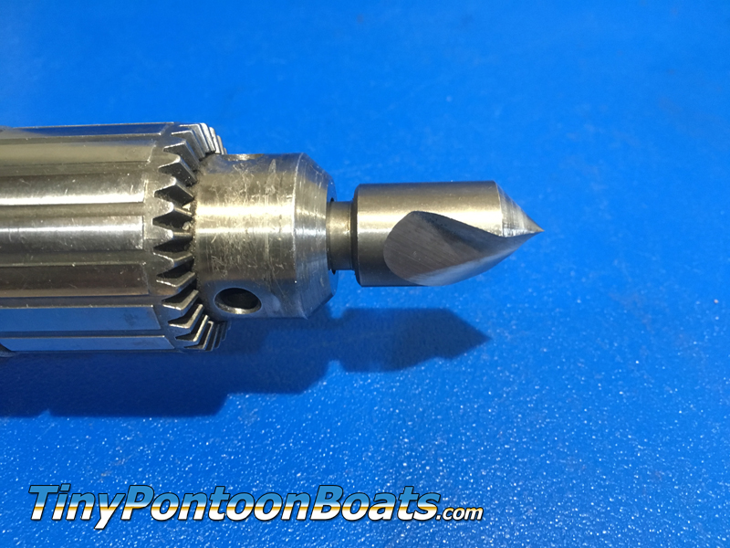
For this operation, you can use a hand-held drill, but we find it much easier and quicker to use a drill press. If you have a drill press, you will need to use a spacer block, such as a piece of 2" x 4" lumber, to make the material surface level. If using a hand-held drill, be careful to keep the drill bit perpendicular to the surface you are drilling through. You can't undrill holes, so take your time. After drilling the holes, they must be deburred. We like to use a countersink drill bit for this, but a little bit of sand paper or a file will do the trick as well.
|
|
|
STEP 9
Clamp the main beams back onto the saw horses in the same orientation as before and place the floats back onto the main beams, matching up the numbers you marked in step 6. Place the ratchet straps back over the floats and tap the floats into position so that the holes line up. DO NOT INSERT THE BOLTS YET.
|
|
|
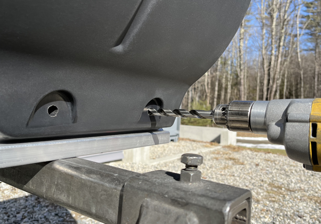
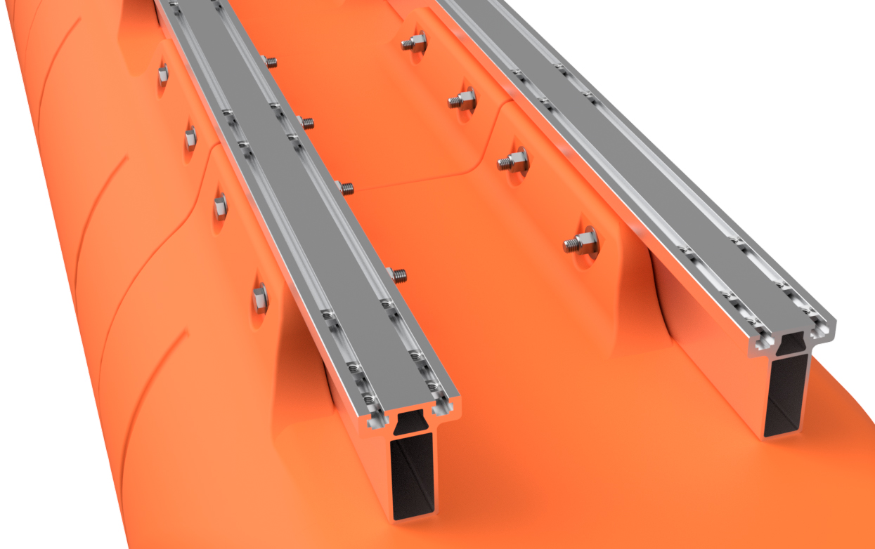
STEP 10
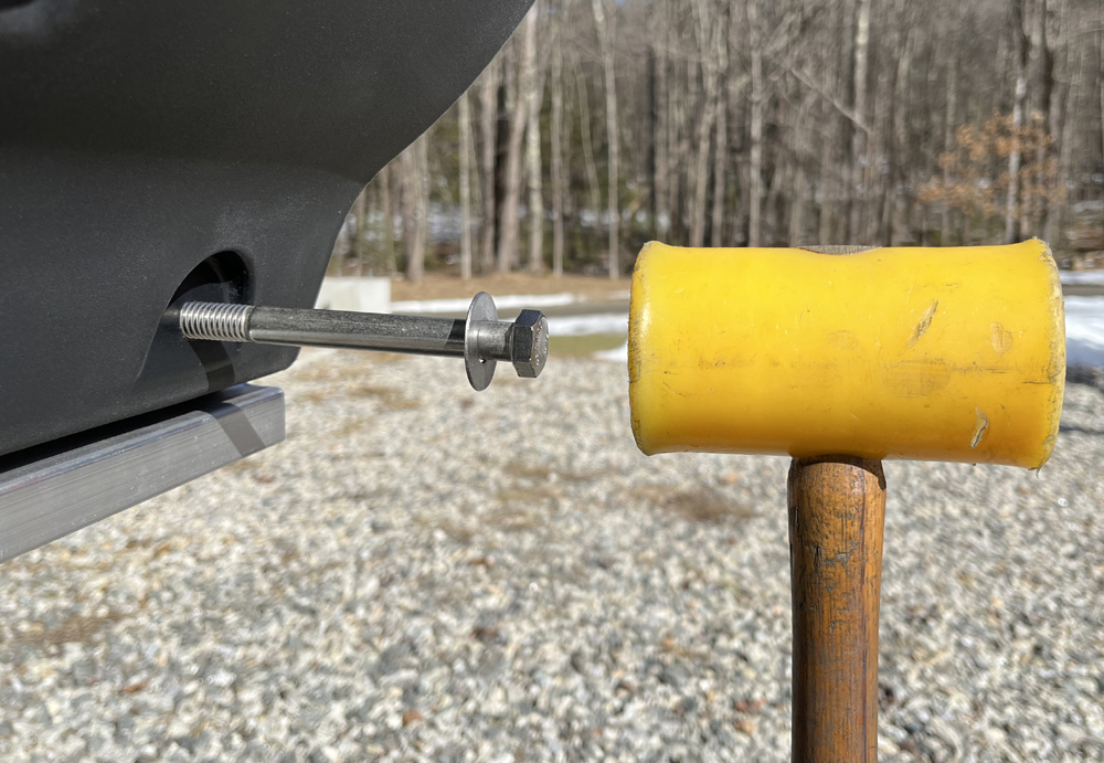
With a 1/2" drill bit mounted in your hand-held drill, start at the back end of the pontoon assembly and drill through one of the the rearmost bolt holes. Drill all the way through both sides of the main beam on that side of the float. You will be drilling inward from the side of the float. When doing this, go slowly, as your drill bit should only be clearing chips and verifying hole alignment, not drilling a new hole.
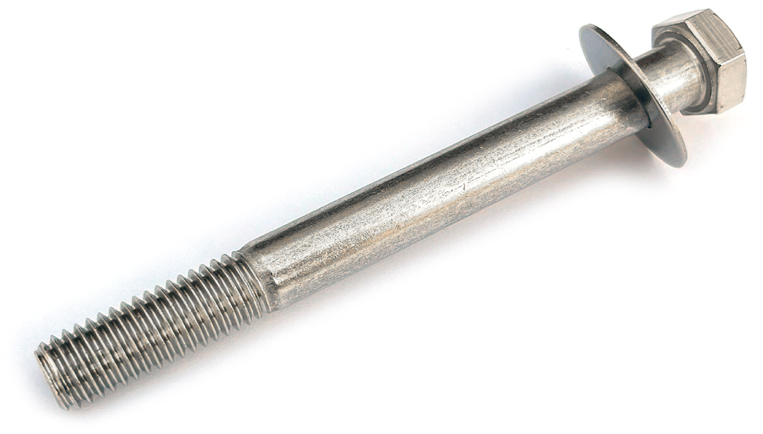
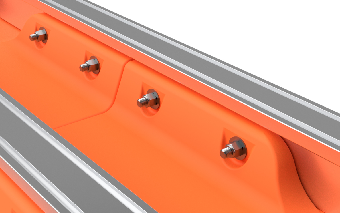
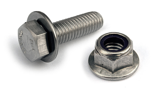
Insert one of the 1/2" x 5" hex bolts with a 1/2" flat washer from the outside position, and tap it through the hole with a hammer. We prefer to use a plastic hammer for this. Drill through the next hole and insert a bolt with washer. Do this on both sides of the pontoon assembly until every float has bolts installed through each hole on both sides of the float. DO NOT INSTALL THE NUTS YET.
|
|
|
STEP 11
Remove the ratchet straps and flip the pontoon so that it's right side up. As the float will be heavy at this point, please be careful when doing this. When we build boats at Tiny Pontoon Boats, this is when we remove the pontoon assembly from the saw horses and place it on a couple pieces of scrap carpeting on our shop floor. We find it much easier to complete this step with the pontoon on the floor.
Using a rag, remove any chips from the exposed threads of the bolts you just inserted through the floats. Place 1/2" flat washers over each of the bolts. DO NOT INSTALL THE NUTS YET. Using the included Loctite capsules (blue medium strength Loctite type 242), apply a little bit of the thread locker to each of the bolts. Your kit has 3 capsules for every 4 float bolts, so more than enough is included. The Loctite lubricates the threads, makes the nuts more secure, and is 100% required. DO NOT SKIP THIS STEP. Thread 1/2" lock nuts onto each of the bolts and tighten the nuts until the mounting flanges on the floats start to flex inward. We do not have a torque specification beyond this. 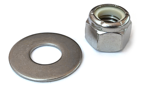 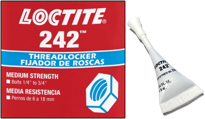
|
|
|
STEP 12
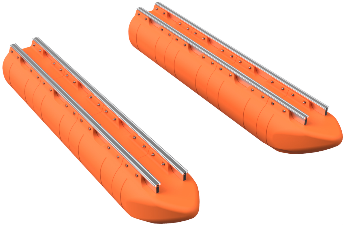
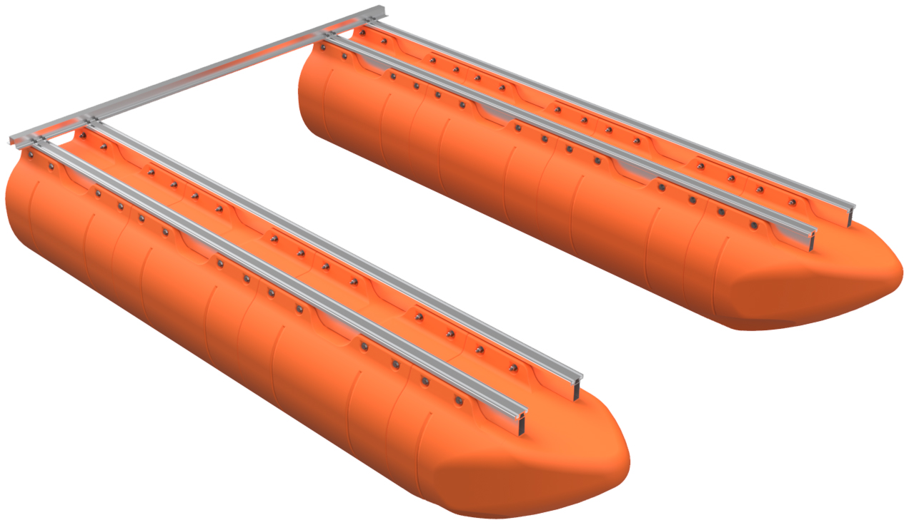
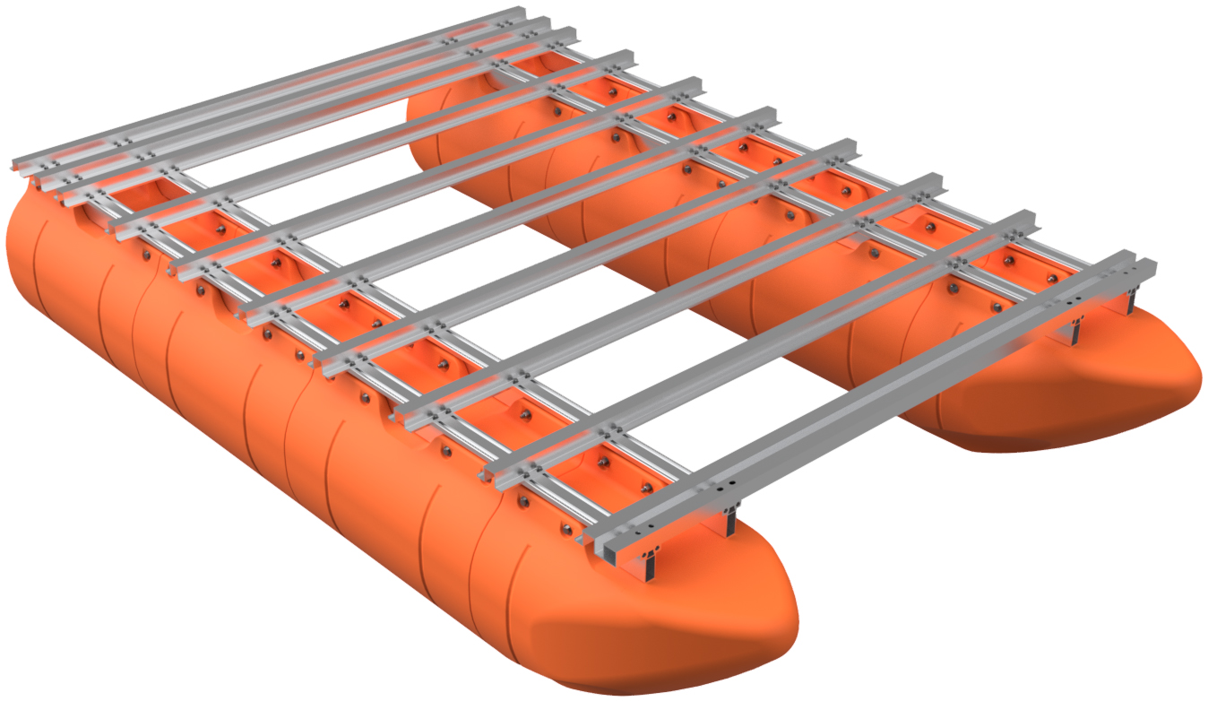
Place the completed pontoon aside and repeat steps 1 through 11 to build your second pontoon assembly. Place your two pontoon assemblies on a flat surface so that they are about 65" on center for 7' wide boats (69" if you purchased a 7' wide kit with our aluminum decking packge) and 74" on center for 8' wide boats.
|
|
|
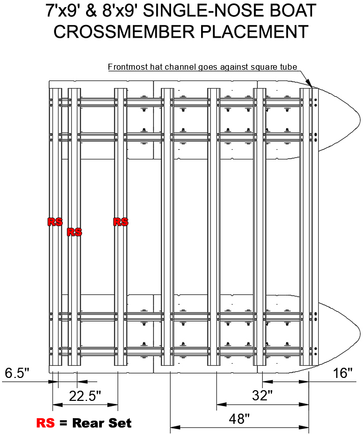
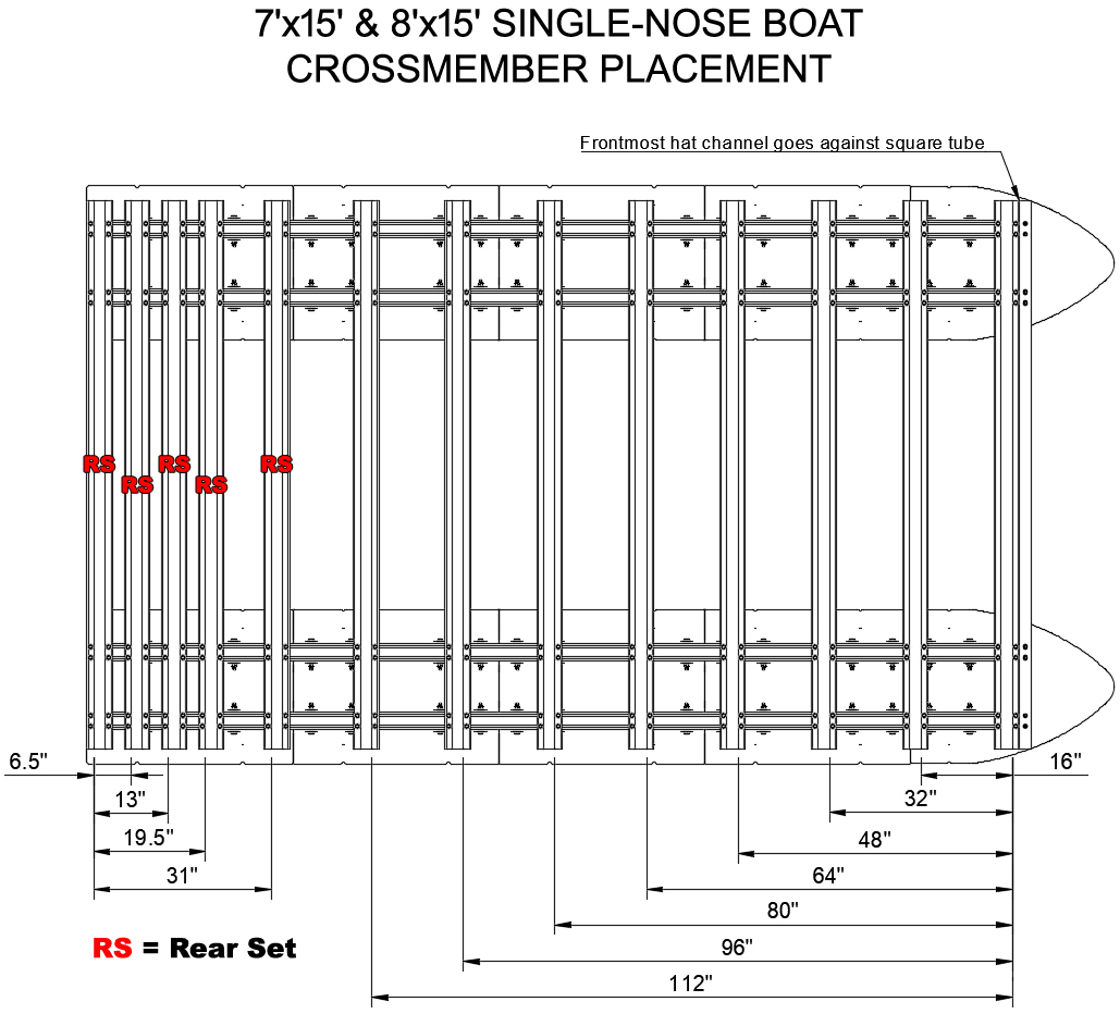
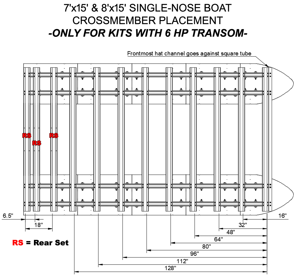
CROSSMEMBER PLACEMENT DIAGRAMS:
Moving forward, you will have to reference the appropriate crossmember placement diagram below. If possible, print the diagram or have it handy on a mobile device as you will need to reference it throughout the remaining assembly. The diagram is particularly important to follow if you purchased a railing kit for your boat, as bolt holes are pre-drilled in the fence panels and must line up with the crossmembers of your frame. Be careful and double-check all crossmember placement before tightening bolts.
The crossmember placement diagrams have "Rear Set" noted on the rearmost 3 or 4 crossmembers for each boat. If you purchased a transom (motor mounting bracket) with your boat kit, there will be 3 or 4 crossmembers in your frame system that have "Rear Set" written on them. The rear set of hat channels will have bolt holes for mounting your transom and must go at the rear of the boat, as indicated by your diagram. If you did not purchase a transom with your boat kit, or if you purchased a set of in-line transoms with your kit, all the hat channels will be identical and any hat channel can go in the rear set position. NOTE:
If you purchased lifting brackets AND in-line transoms, the rearmost hat channels are to be placed 12" in from the rear end of the main beams and the frontmost crossmembers are to be placed 4" in from the front ends of the main beams. When purchasing this set-up, you will be provided with a custom crossmember placement diagram via email.
|
|
|
STEP 13
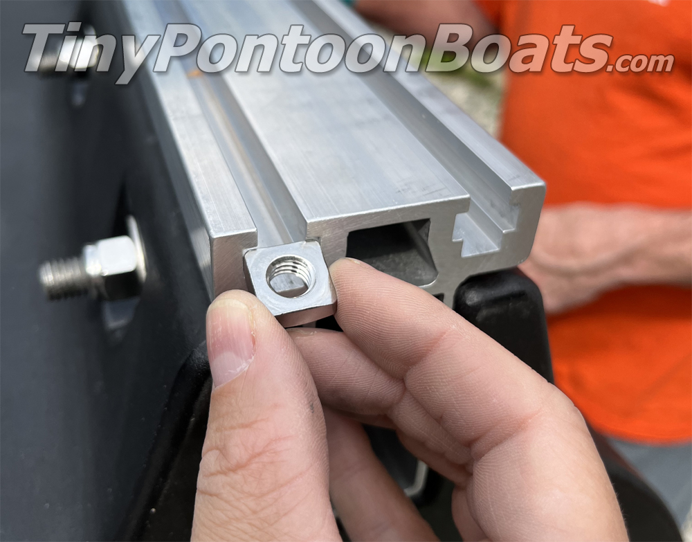
Each hat channel crossmember requires 16 sets of nuts, bolts, and washers for installation. The front crossmember is the only crossmember that is a square tube, not a hat channel. Slide 2 square nuts into each main beam slot for each "rear set" crossmember shown on your crossmember placement diagram. Position the nuts in the approximate locations of each "rear set" crossmember.
|
|

|
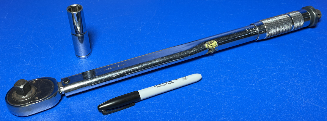
FRAME & ACCESSORY FASTENER TORQUE SPECIFICATIONS
Each of the 3/8" diameter bolts for the frame crossmembers and accessories (transoms, lift plates, tie-down plates, trailer winching plates, etc.) require the proper amount of torque to ensure that they are fastened securely and retain full strength. The proper amount of torque for all 3/8" nuts and bolts from this point forward is 55 foot pounds. DO NOT TORQUE BEYOND THIS SPECIFICATION. From this point forward when we say to fully torque or fully tighten a bolt or nut, we are referring to the 55 foot pound specification, and it is good practice to draw a line on the head of the bolt with a marker after to indicate it has been torqued properly. If you do not own or have access to a torque wrench, be careful not to apply too much torque to the bolt heads. If you do not own one, or do not want to purchase one for your assembly, many autopart stores will allow you to borrow one at little or no cost.
|
|
|
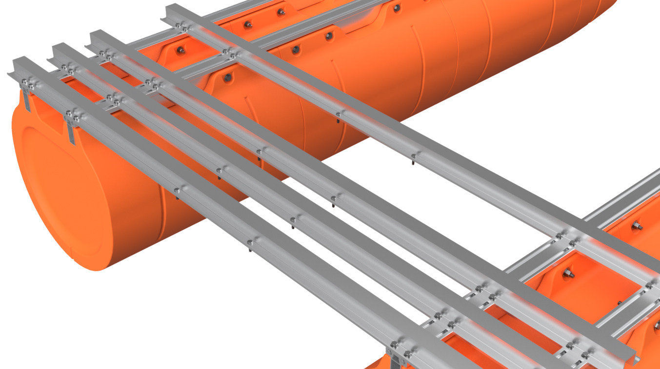
STEP 14
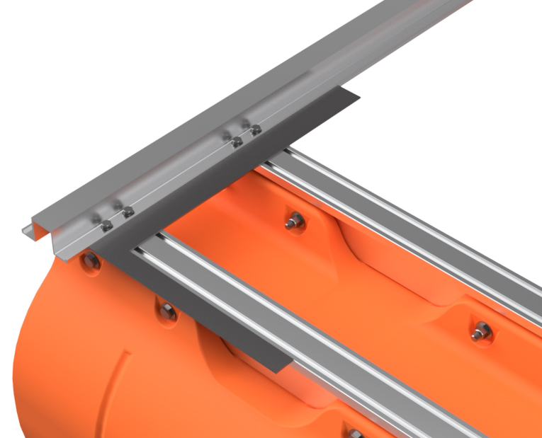
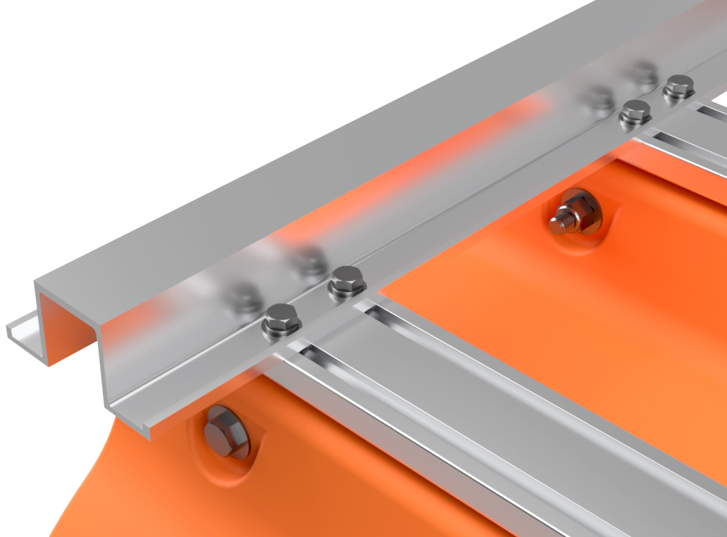
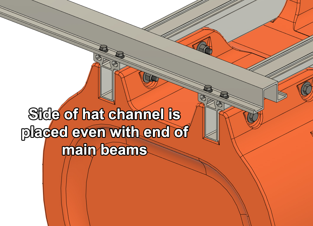
Loosely bolt the rearmost hat channel crossmember across your two pontoon assemblies using the 3/8" x 7/8" hex bolts, 3/8" lock washers, and 3/8" SAE flat washers. If you purchased a transom (other than in-line transoms), make sure to select a hat channel that has "Rear Set" written on it. Adjust the hat channel so it is even with the ends of the main beams and use a square to ensure that one of the pontoon assembly main beams is square with the hat channel. Completely tighten the bolts on that side of the hat channel. Adjust the other pontoon assembly to be square with the hat channel and leave the bolts finger tight.
NOTE:
If you DID purchase in-line transoms with your boat kit (with or without lifting plates), the rearmost crossmember will be placed 12" in from the end of the main beams, not even as shown. 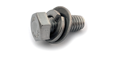
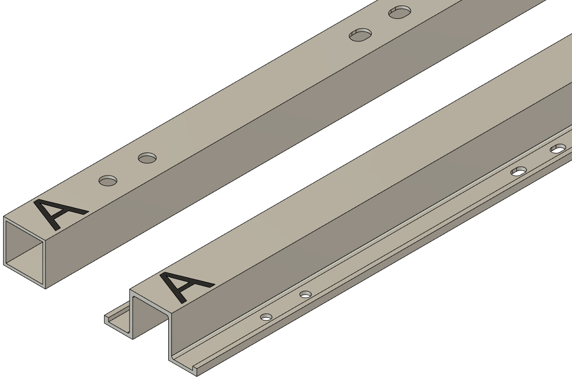
NOTE:
Crossmembers have "A" written on one end. Be sure to place the marked ends of the crossmembers on the same side of the boat (doesn't matter which side). When the hole pattern is machined in each crossmember, this is the end that is referenced on the machine cutting the holes. Placing the "A" end of all the crossmembers on the same side of the boat ensures perfect alignment of all the mounting holes.
|
|
|
STEP 15
Loosely bolt on the remaining rear set hat channel crossmembers and place them as shown on your crossmember placement diagram. Adjust the pontoons as necessary to ensure that the rearmost hat channel is square with the main beams on both pontoons, and completely tighten the loose rearmost hat channel bolts. Leave all but the rearmost hat channel bolts loose for now.
|
|
|
STEP 16
If you DID NOT purchase a transom, transoms, or trolling motor mount with your boat kit, skip this step and move onto step 18.
If you purchased a center-mount (mounts between the flaots) transom or trolling motor mount with your boat kit, locate the bag of hardware labeled "transom mounting hardware" or similar and move to the next step.
|
|
|
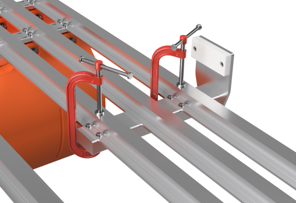
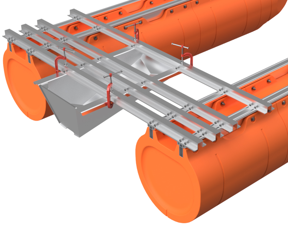
STEP 17
Select the 3/8" x 1 1/4" hex bolts from your "transom mounting hardware" bag, and insert them through the holes in the center of your rear set hat channels. Line up the hanging bolts with the mounting holes in your transom or trolling motor mount. Clamp your transom or trolling motor mount into place with C-clamps. DO NOT INSTALL NUTS ON THE HANGING BOLTS IN THIS STEP. All the bolt holes are slightly oversized, but you may have to make minor adjustments to the crossmembers to ensure that all the holes line up. You now have a bolt in every mounting hole in your transom or trolling motor mount, so you can be certain that all the holes line up for final installation later on. Tighten all of the rear set hat channel bolts and remove your transom or trolling motor mount. Place the 3/8" x 1 1/4" hex bolts back in the "transom mounting hardware" bag.
|
|
|
STEP 18
Referencing your crossmember placement diagram, slide groups of four 3/8" square nuts into each pontoon main beam at the approximate locations of the remaining hat channel crossmembers shown on your crossmember placement diagram. As your front crossmember is a 2" square tube with a total of 8 bolt holes, slide one additional square nut into each main beam slot at the front of your boat. The center of these nuts should be about 1" from the end of the main beams.
|
|
|
STEP 19
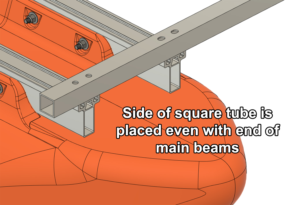
Place the 2" x 2" square tube front crossmember across the front end of your pontoon main beams and place the side of the tube with the larger holes upward. Position the square tube so that front edge is even with the ends of the main beams. Align the square nuts at the front of the main beams with the bolt holes in the square tube.
NOTE:
|
|
|
STEP 20
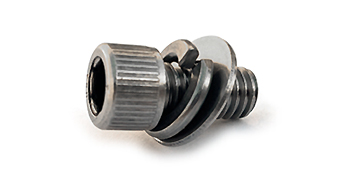
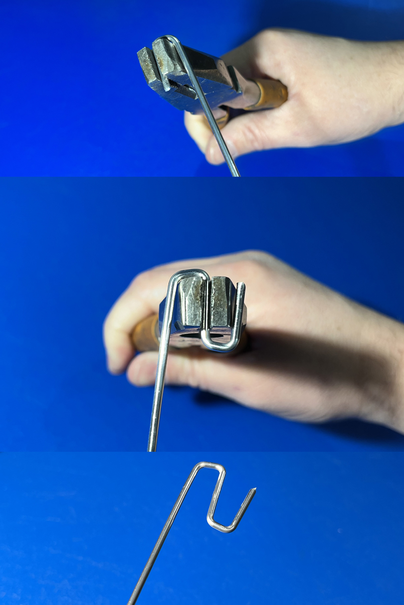
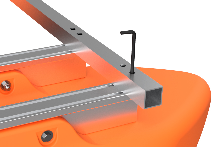
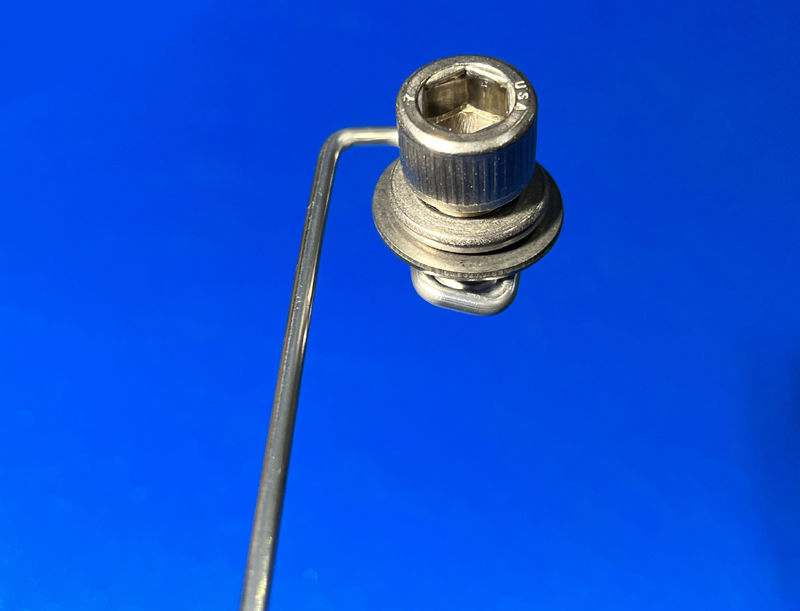
Locate the 3/8" x 3/4" socket head cap screws (bag may say "Allen bolts) and place a 3/8" lock washer and 3/8" SAE flat washer on eight of the bolts. To install the bolts and washers, you need to make a special tool from a length of thick wire, such as a coat hanger or a piece of welding wire. When we build boats at Tiny Pontoon Boats, we use 3/32" diameter aluminum TIG welding rod. This special tool is for inserting the bolt assemblies through the ends of the square tube front crossmember.
Using a pair of pliers (we use lineman pliers), bend a hook on the end of your length of wire, and then bend the hook in the opposite direction. This tool is used to hold the socket head cap screw bolt assembly.
|
|
|
STEP 21
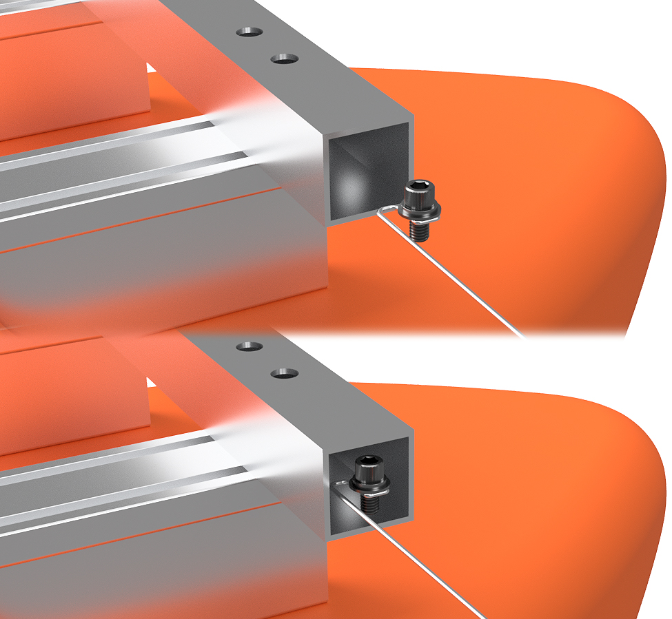
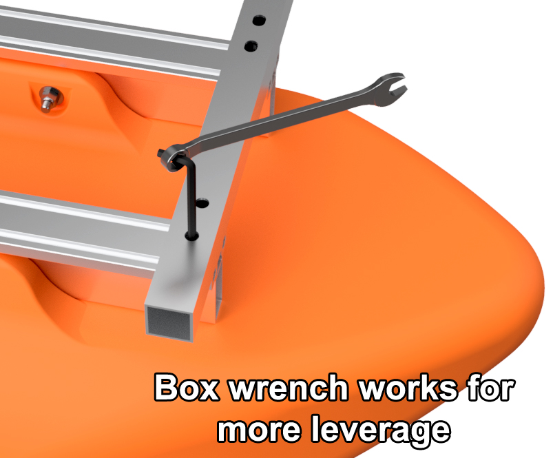
Adjust your wire tool's hook so that it can hold the socket head cap screws. Using the wire tool, insert a bolt with washers into the end of the square tube crossmember and line up the bolt assembly with the innermost hole. Use a 5/16" hex key wrench to loosely thread the bolt into the square nut below. Work from the inner holes out and install bolt assemblies into each of the 8 bolt holes in the square tube. Double-check the alignment of the square tube with the ends of the main beams and tighten all the bolts. A great way to get extra leverage on your hex key wrench is to use a box wrench.
|
|
|
STEP 22
Bolt the frontmost hat channel crossmember onto your boat. This crossmember goes right against the square tube crossmember and bolts on with the same 3/8" bolts and washers as the prior installed hat channels.
|
|
|
STEP 23
Bolt all the remaining hat channel crossmembers onto the frame. Working from the rear of the boat forward, position a crossmember, check your measurement against the crossmember placement diagram, and bolt it down loosely with the same 3/8" x 7/8" bolts, lock washers, and flat washers as before. Move onto the next hat channel until all of your crossmembers are on your boat.
Once again, working from the rear of the boat forward, tighten every crossmember bolt. We like to use a marker to draw a line across every bolt head that we have fully tightened to ensure no bolts are missed.
|
|
|
THIS PART OF YOUR PROJECT IS COMPLETE!
The frame and floats system for your Tiny Pontoon Boat is now complete! Pat yourself on the back as you did a great job. If you purchased a transom or trolling motor mount for your boat, move onto the section below.
|
|
TRANSOM INSTALLATION
FOR CENTER-MOUNT TRANSOMS This section is for center-mount transoms (mounted between the floats). Please see the section below for in-line transoms.
With your frame assembled, the next step is to install the decking or transom. If you purchased our aluminum decking package with your boat kit, the final installation of your transom or trolling motor mount happens AFTER the decking is installed. Decking installation instructions are listed HERE. If you are using marine grade plywood for decking, you can install the transom before the plywood is installed. TROLLING MOTOR MOUNT:
6/20/30 HP TRANSOMS:
|
|
|
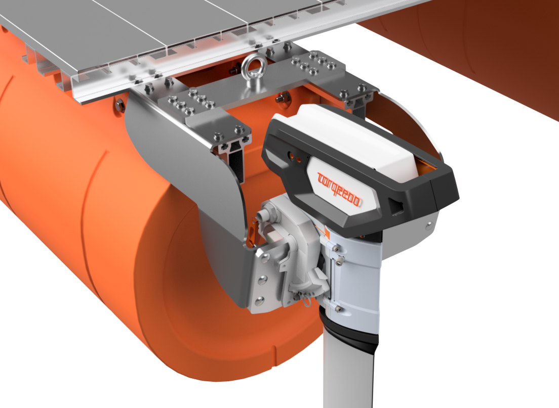
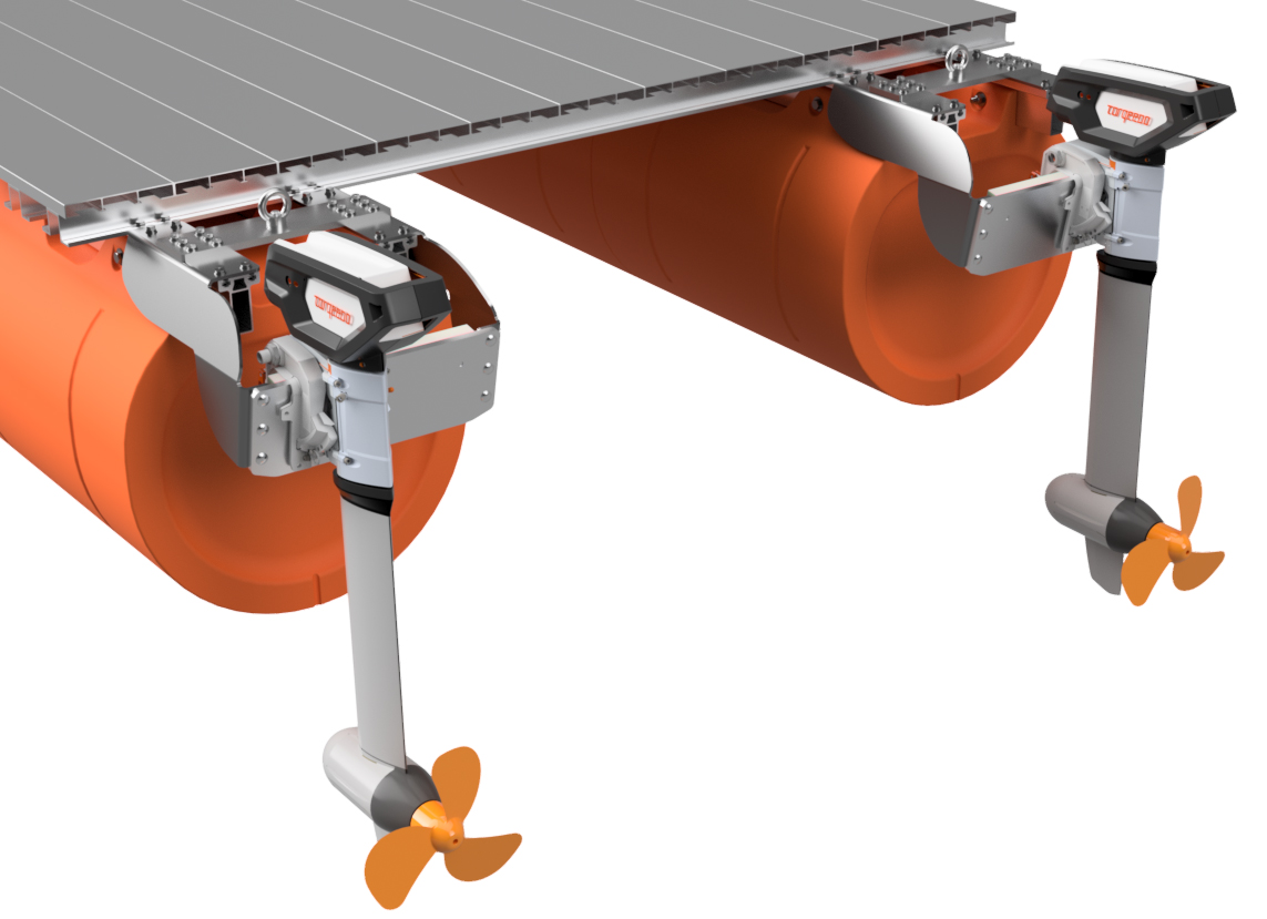
IN-LINE TRANSOM INSTALLATION
If you purchased in-line transoms with your boat kit, with your frame now assembled, the next step is to install your transoms. If you also purchased our aluminum decking package, this portion of your assembly can happen before or after transom installation. Decking installation instructions are listed HERE.
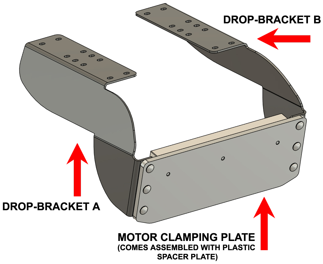
Our in-line transoms have three main parts. Drop-bracket A, Drop-bracket B (mirror of Drop-bracket A), and the Motor Clamping Plate. When purchaseing a set of our in-line transoms, you will get two of each of these parts with hardware. |
|
|
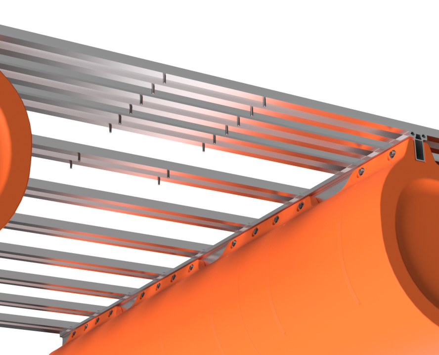
IN-LINE TRANSOMS
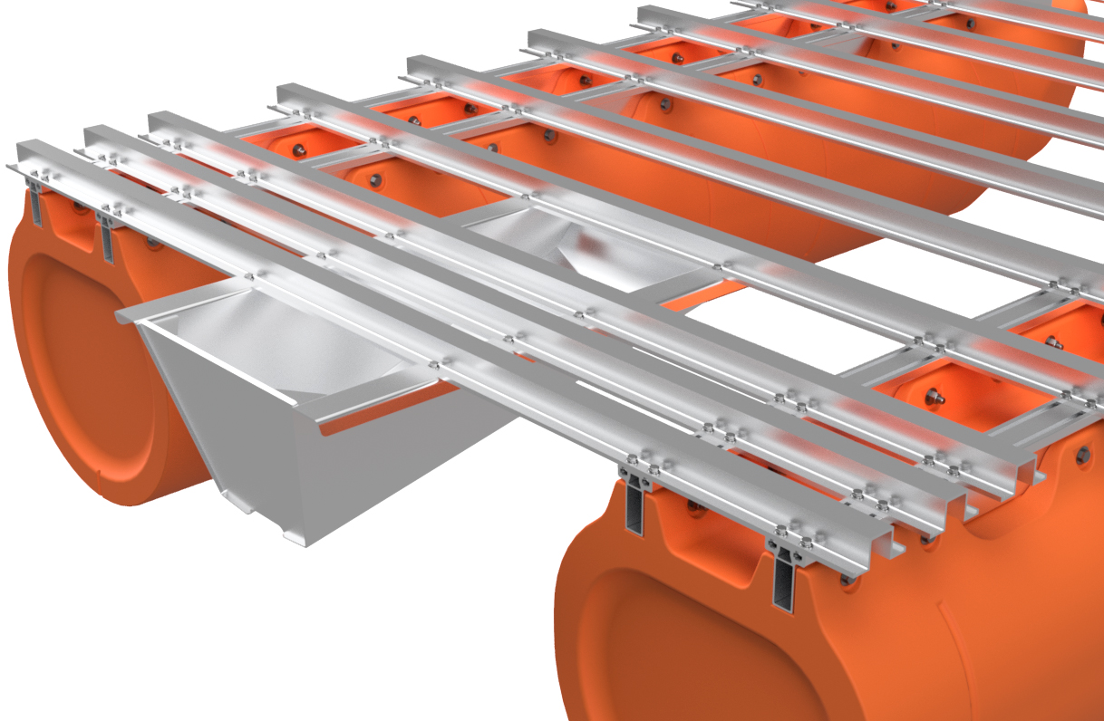
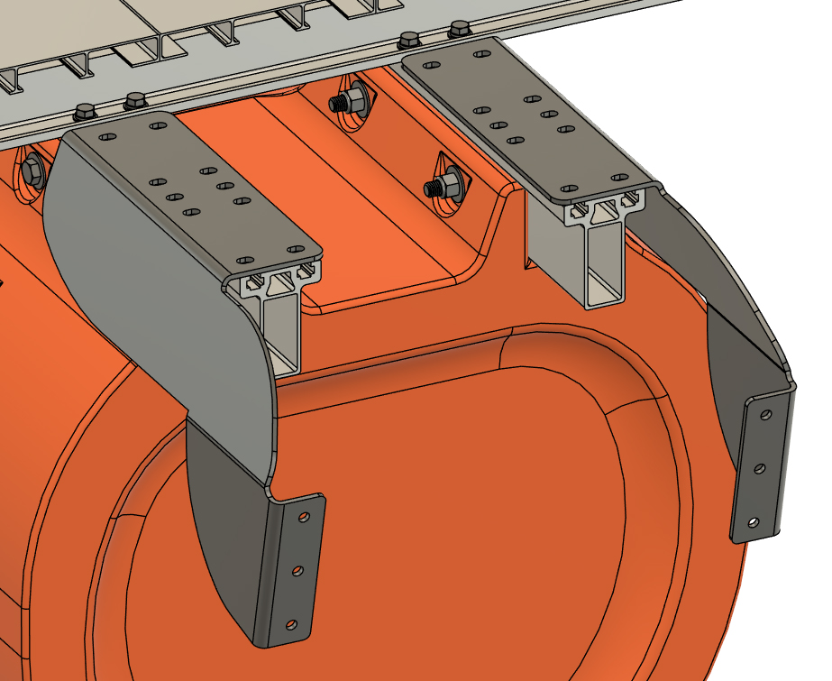
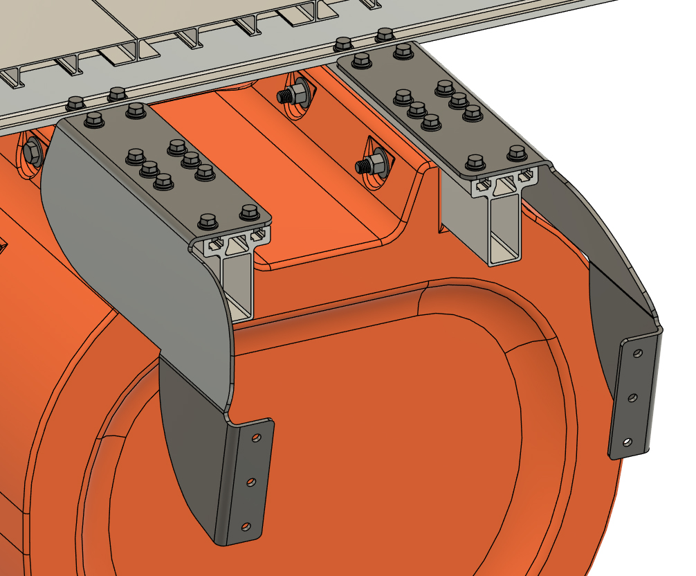
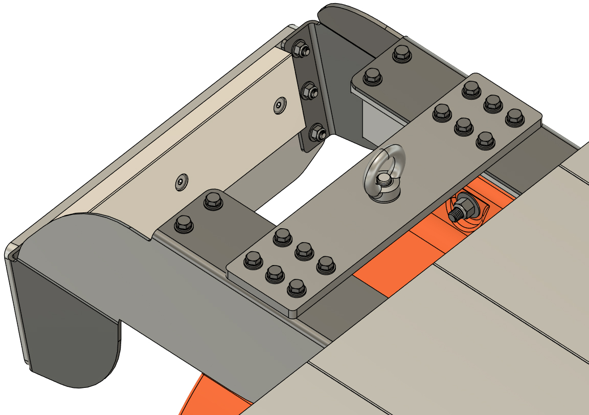
STEP 1 Our in-line transom set is designed to be used with or without our lifting brackets. If you DID NOT purchase the lifting plate set, LOOSELY bolt one of DROP-BRACKET A and DROP-BRACKET B onto the rear end of either pontoon assembly as shown. The hardware for this will all be in a bag labeled "transom hardware" or similar. Just like with your frame crossmembers, you will need to insert a square nuts into the rear portion of your crossmembers, line the nuts up with the drop-bracket bolt holes, and then LOOSELY install 3/8" x 7/8" hex bolts with lock washers and SAE flat washers as shown.
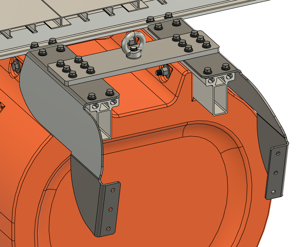
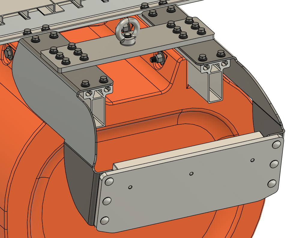
IF YOU DID purchase lifting brackets with your boat kit, LOOSELY install 3/8" x 7/8" bolts with washers at the frontmost and rearmost bolt holes in your drop brackets and then use the included 3/8" x 1 3/8" hex bolts with washers to attach the lifting brackets on top of the transom drop brackets as shown. DO NOT TIGHTEN THE BOLTS YET. 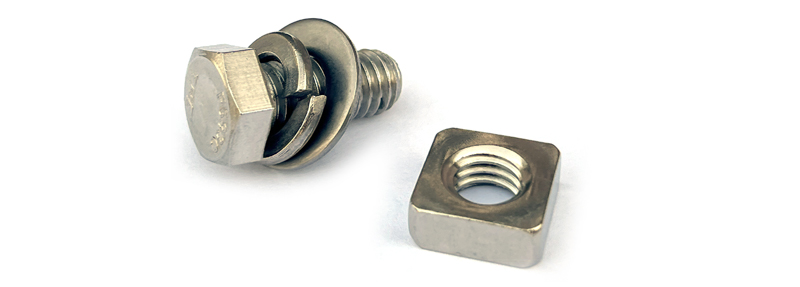
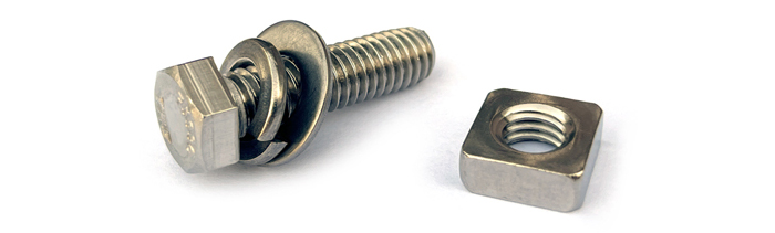
3/8" x 1 3/8" hex bolt, washers, and nut:
|
|
|
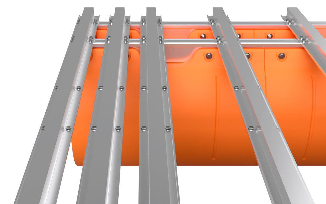
IN-LINE TRANSOMS
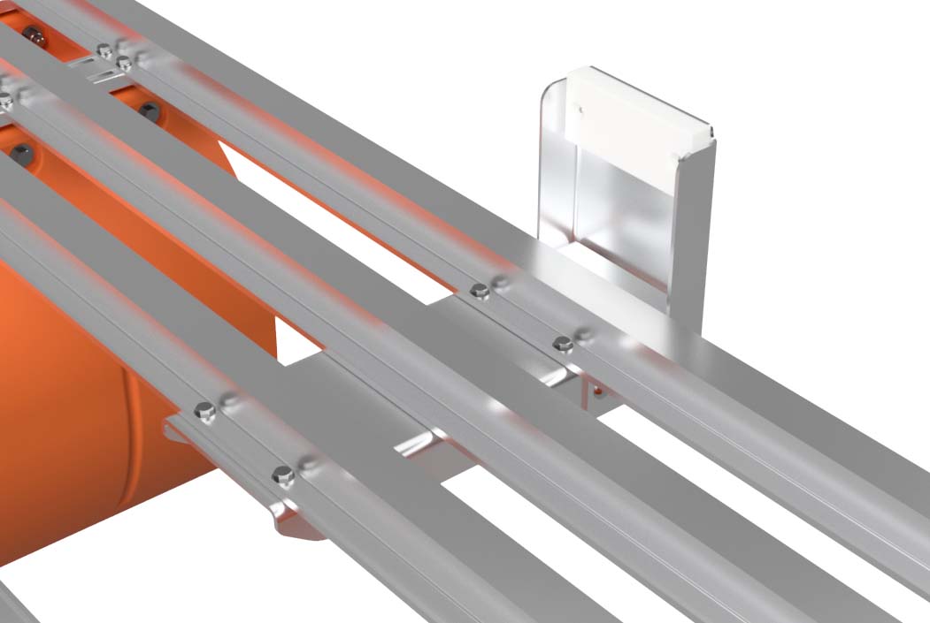
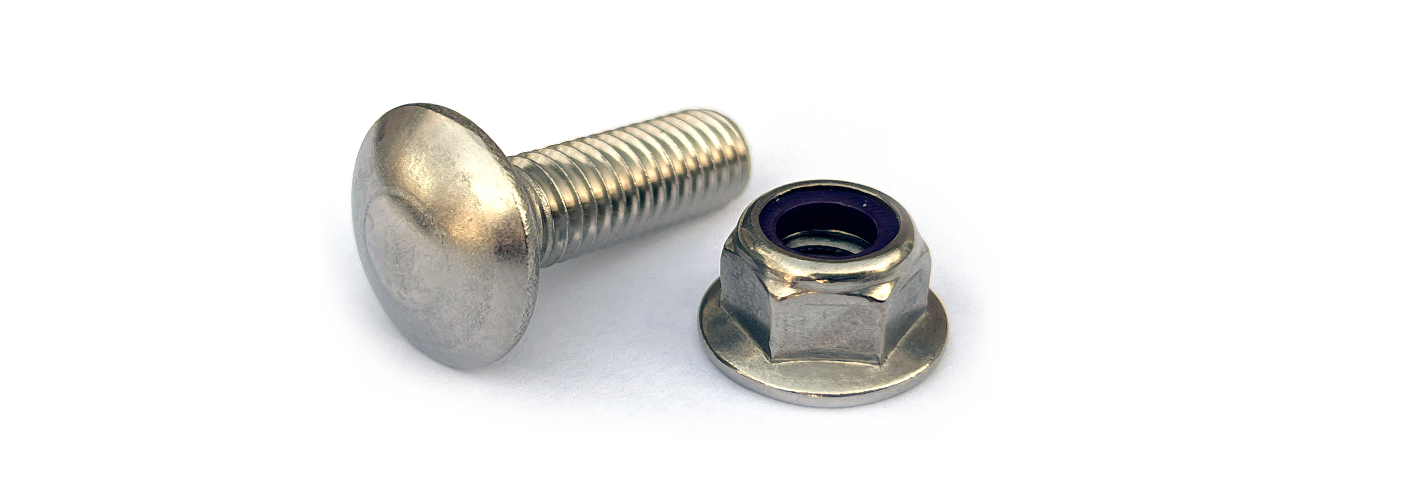
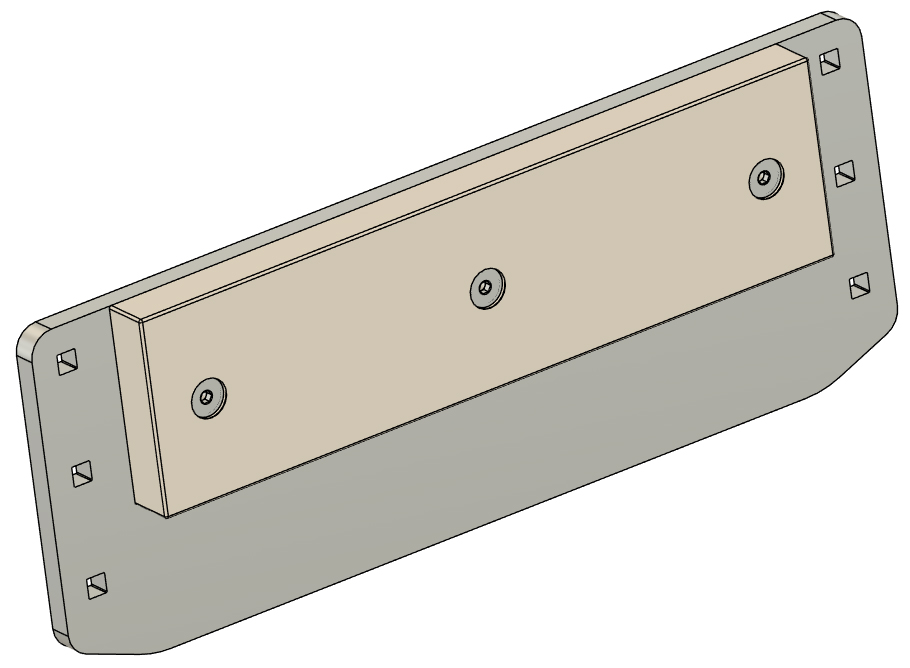
STEP 2 The last parts to attach are your Motor Clamping Plates. Using the 3/8" x 1 1/4" carriage bolts from your bag of transom hardware, attach the Motor Clamping Plates as shown. The carriage bolts fit into the square holes on the Motor Clamping Plates, the bolts go through the drop-brackets, and 3/8" flange lock nuts install from the front side of the drop-brackets as shown. Be sure to orient the Motor Clamping Plates so that the pre-installed plastic blocks face the front of the boat.
|
|
|
IN-LINE TRANSOMS
STEP 3 With all your transom fasteners in place, you can now tighten all the nuts and bolts. Torque EVERY nut and bolt that you installed on your transoms to 55 FOOT POUNDS. This is a crutial torque value and you DO NOT want to over-tighten any of these bolts or leave any loose. We like to draw a line on each bolt head with a marker after we torque bolts on an assembly like this. The gives us a visual check that didn't miss any.
With all your bolts properly torqued, you can now clamp your motors onto the boat and this part of your project is complete!
|
|