
|
603-630-5658
|
|
tinypontoonboats@gmail.com
|

|
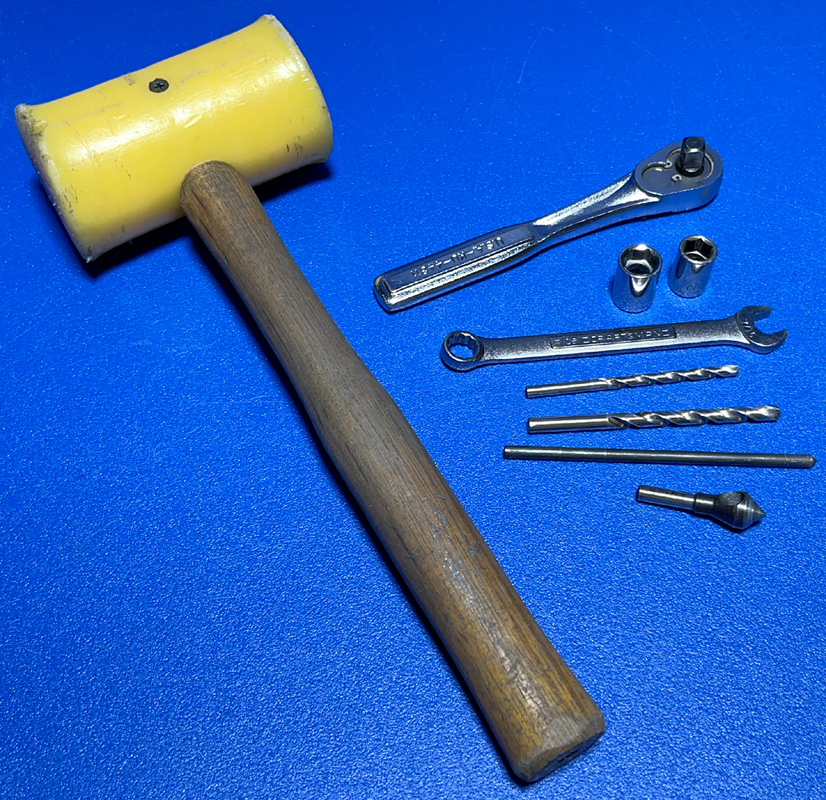
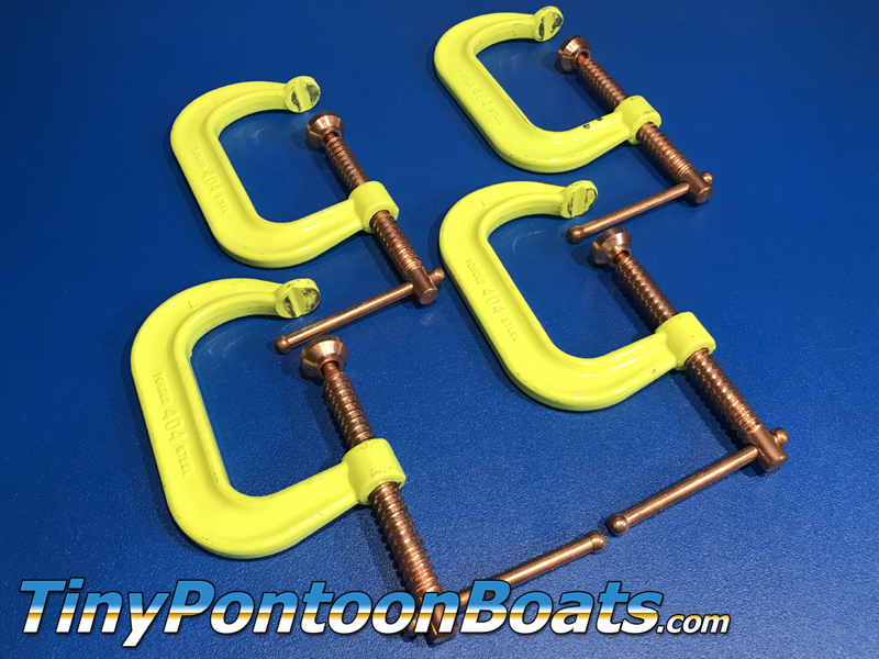
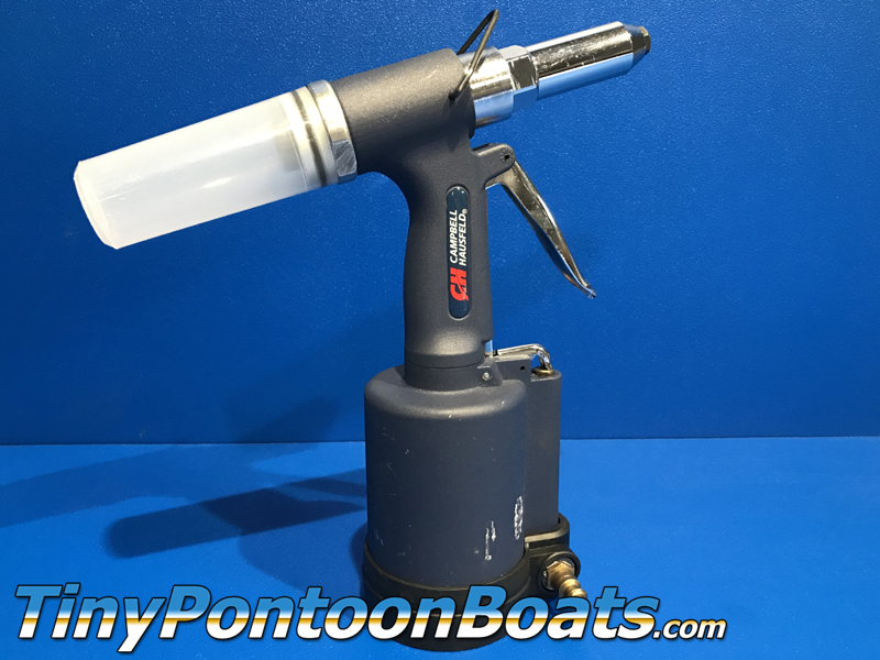
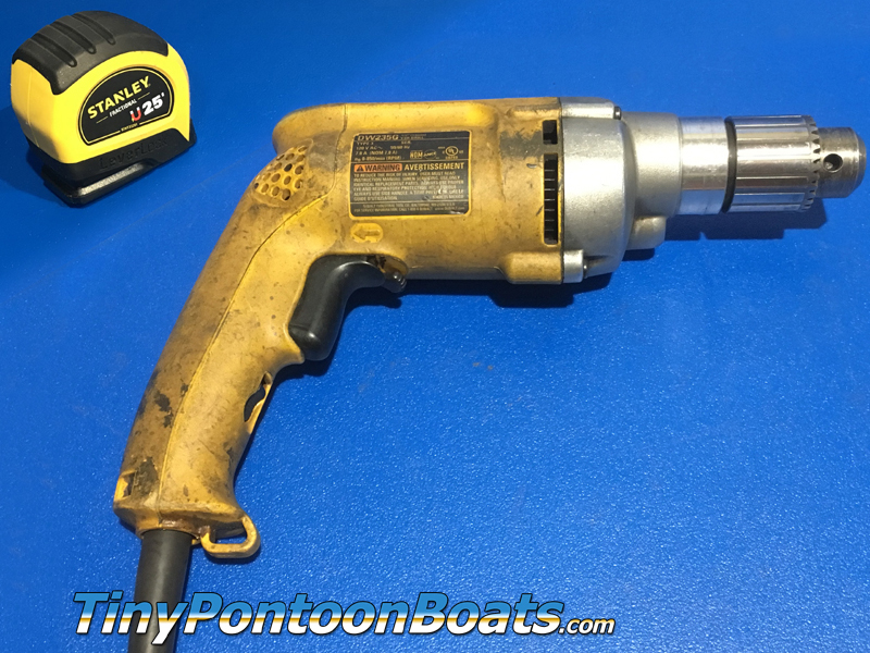
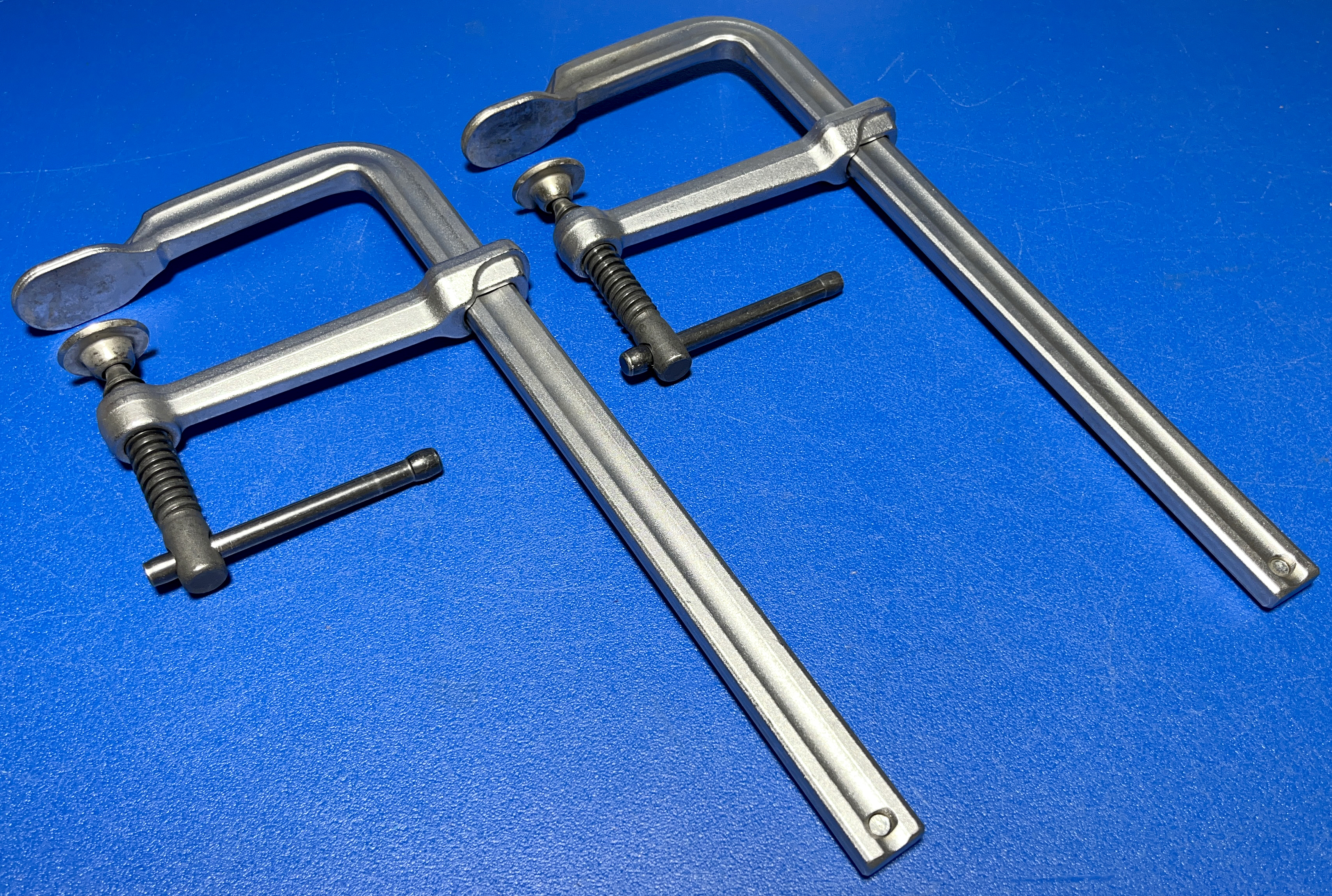
REQUIRED TOOLS
Installation of your full-surround fence system on your blunt work platform is simple and requires some basic tools. Below we have provide a list of everything that you'll need. Most customers will already have the required tools on hand.
|
|

|
STEP 1
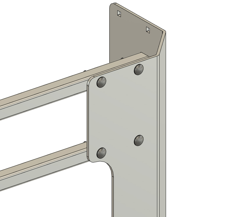
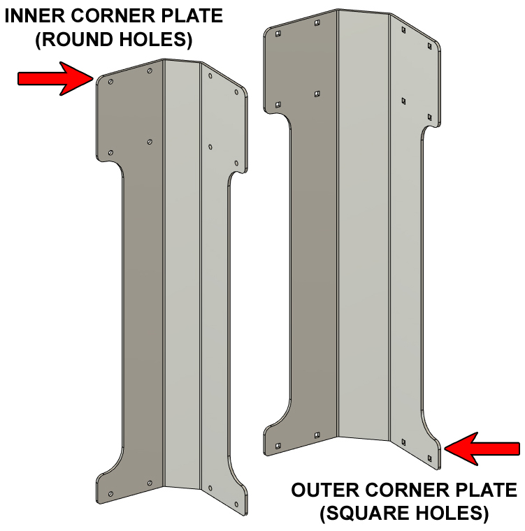
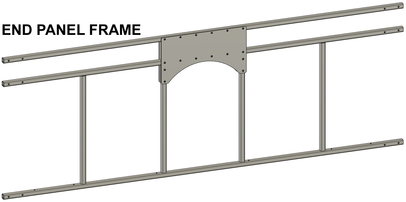
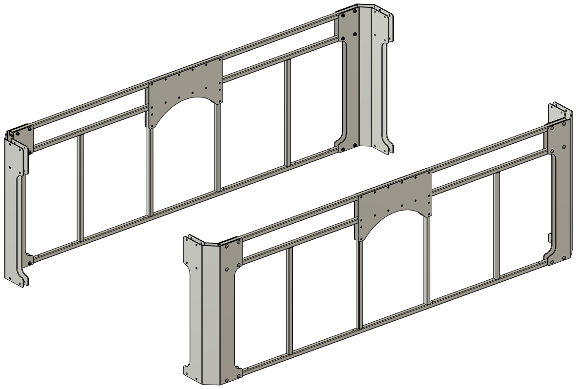
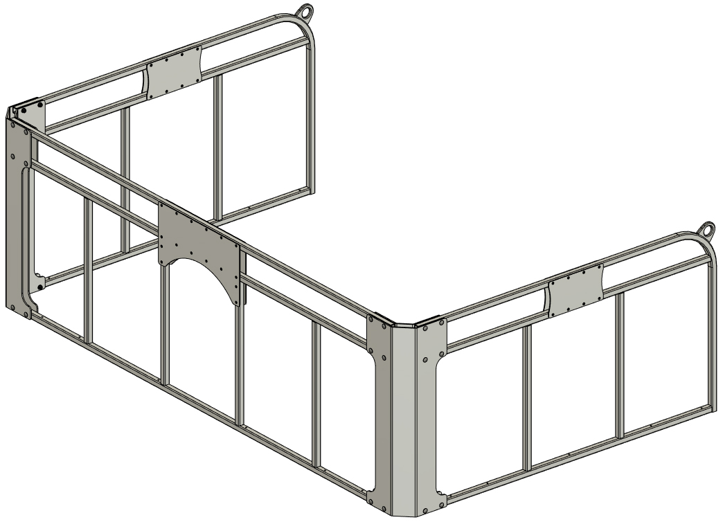
Our full-surround fence systems include components to assemble end panels and side panels, and in this step, we will start assembly of the end panels.
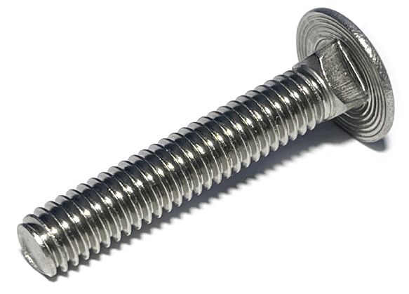
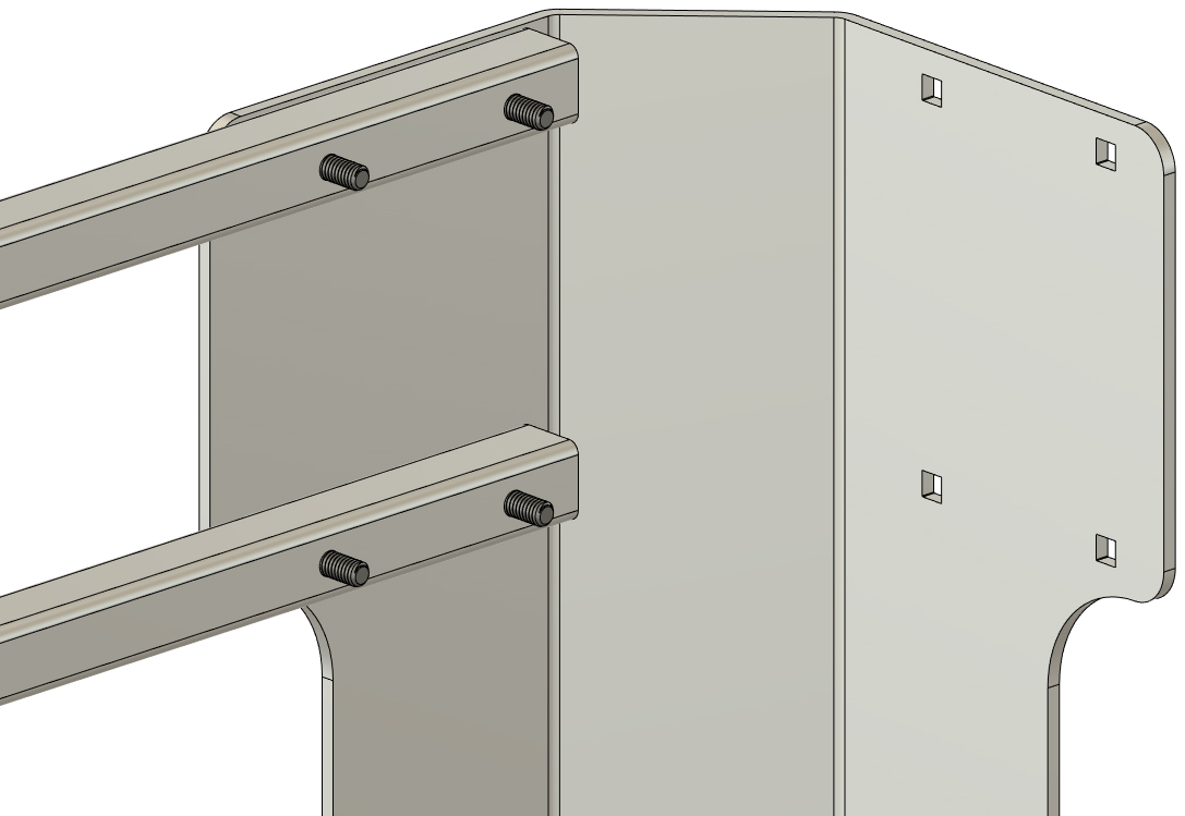
Each kit includes 4 outer corner plates and 4 inner corner plates. The outer corner plates are wider and have square bolt holes to accept carriage bolts. The inner corner plates have round bolt holes. We have pointed out the corner plates and the end panel frames from out kits below. This set of instructions is for our full line of blunt work platform fence systems, so the end panel frames you are working with may have a slightly different configuration. The pictures shown on this page are for our 8'x12' blunt work platform system. Using the 5/16" x 1 3/4" carriage bolts from your hardware kit, connect two of the outer corner plates to one of the end panel frames as shown. You may have to flex the frame tubes slightly to make the bolt holes align. The square portion of the bolts will seat into the square holes of the outer corner plates.
 |
|
|
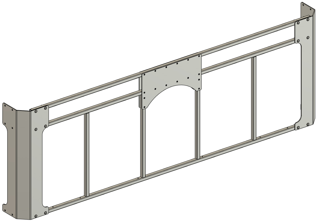
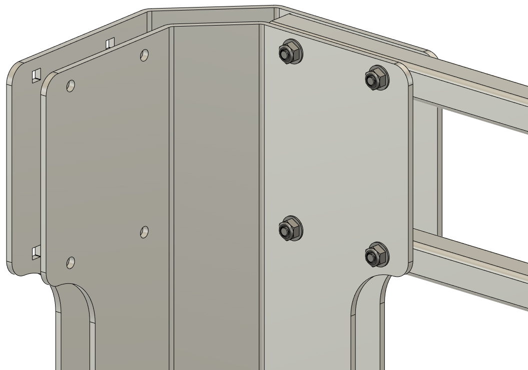
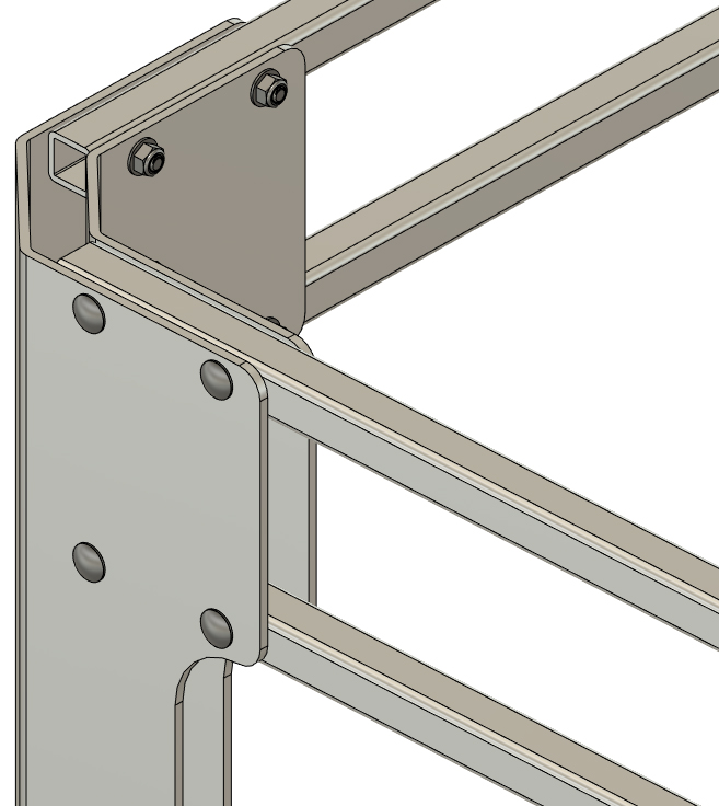
STEP 2
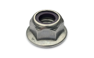
Install an inner corner plate on either side of the end panel as shown and loosly install a 5/16" locknut (do not fully tighten the nuts yet). You now have one fence end panel assembly.
|
|
|
STEP 3
Repeat the steps above to assemble the other end panel and corner plates in your kit.
|
|
|
|
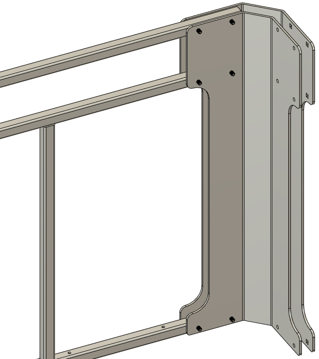
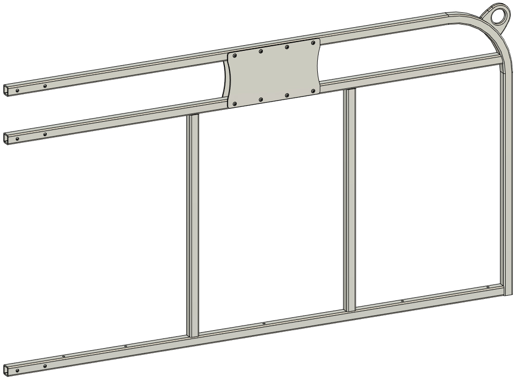
STEP 4
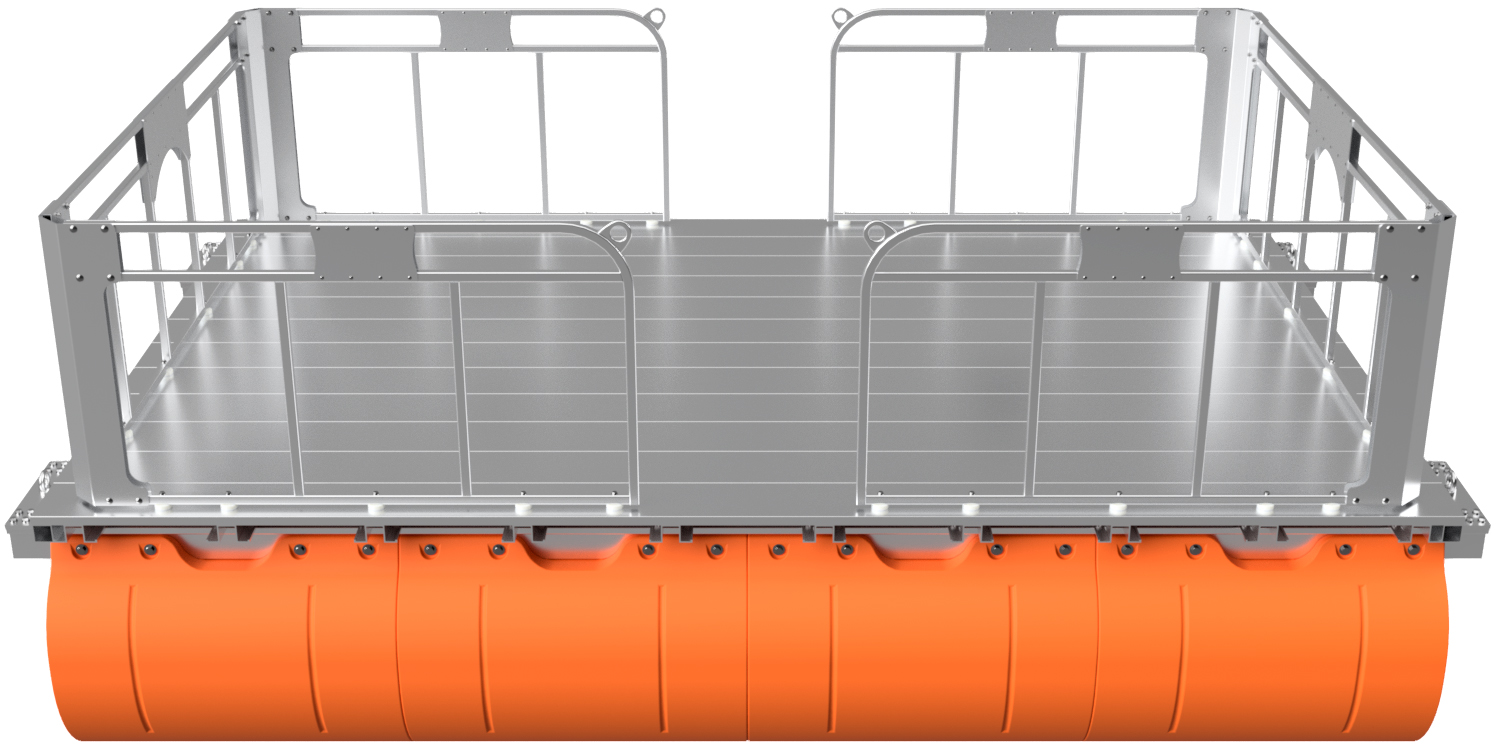
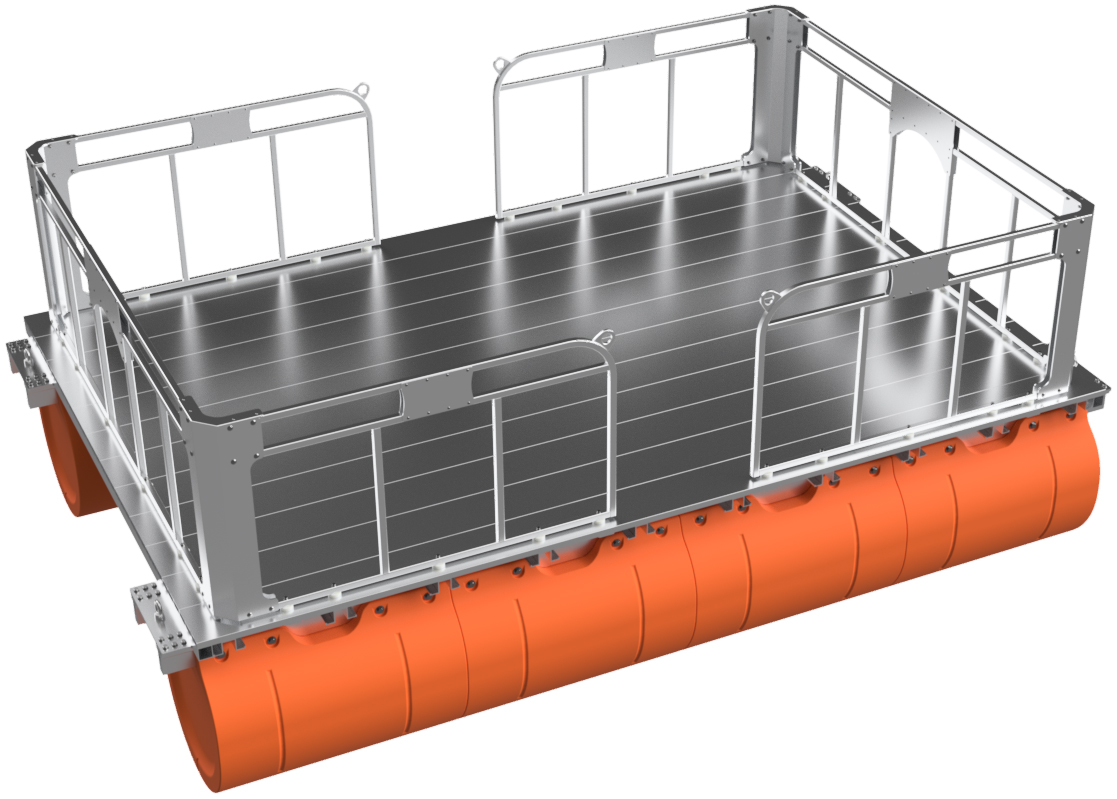
From this point forward, we recommend continuing assembly on the deck of your work platform. For clarity, we are not yet showing the work platform itself.
Your fence system includes four identical side panels, as shown below. Insert a side panel between the corner plates of an end panel assembly as shown, and line up the bolt holes. Install a 5/16" x 1 3/4" carriage bolt through each bolt hole and install 5/16" flange lock nuts onto each bolt. Once you have bolts through every hole in the corner plates, fully tighten the nuts. Repeat this for the three remaining corners. Double-check that all the nuts are tight on each of the four corners.
|
|
|
|
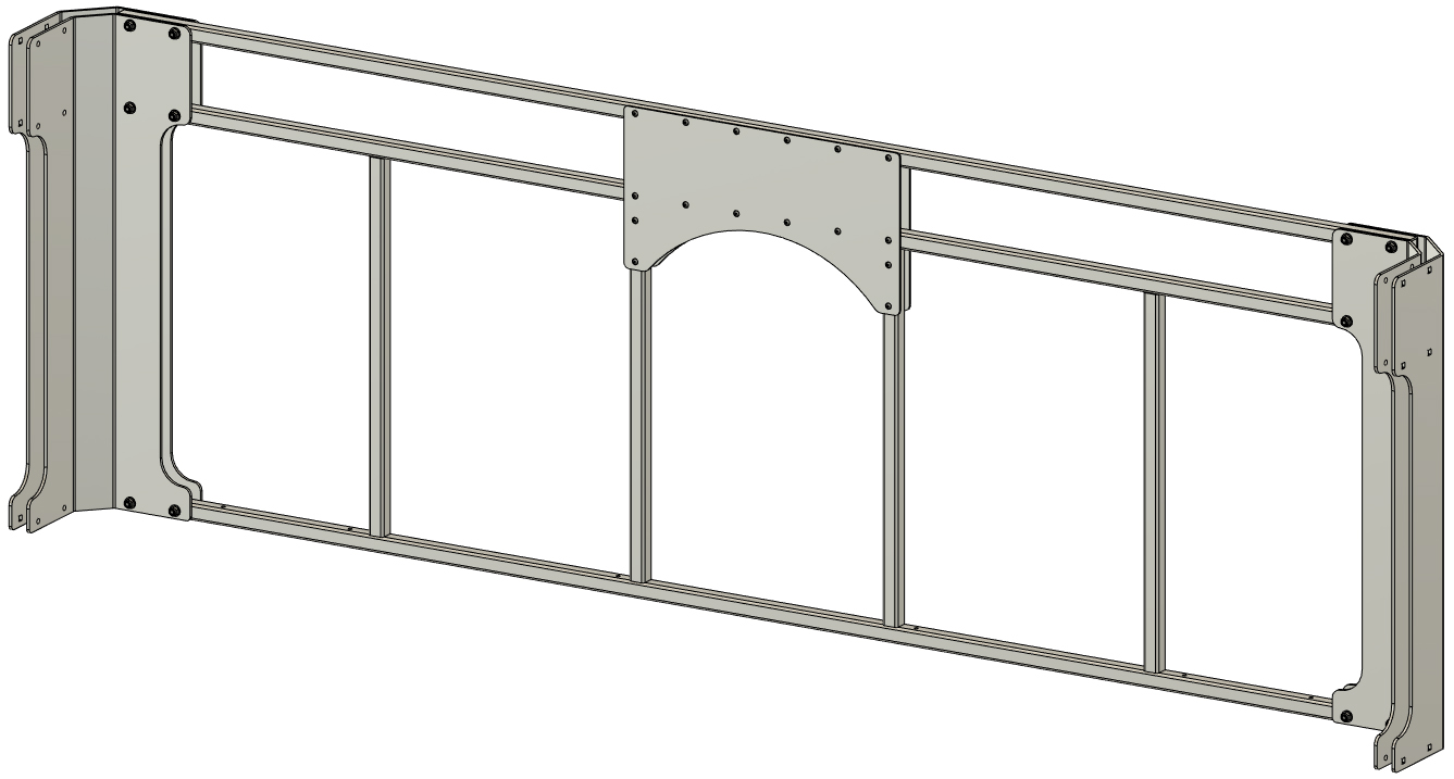
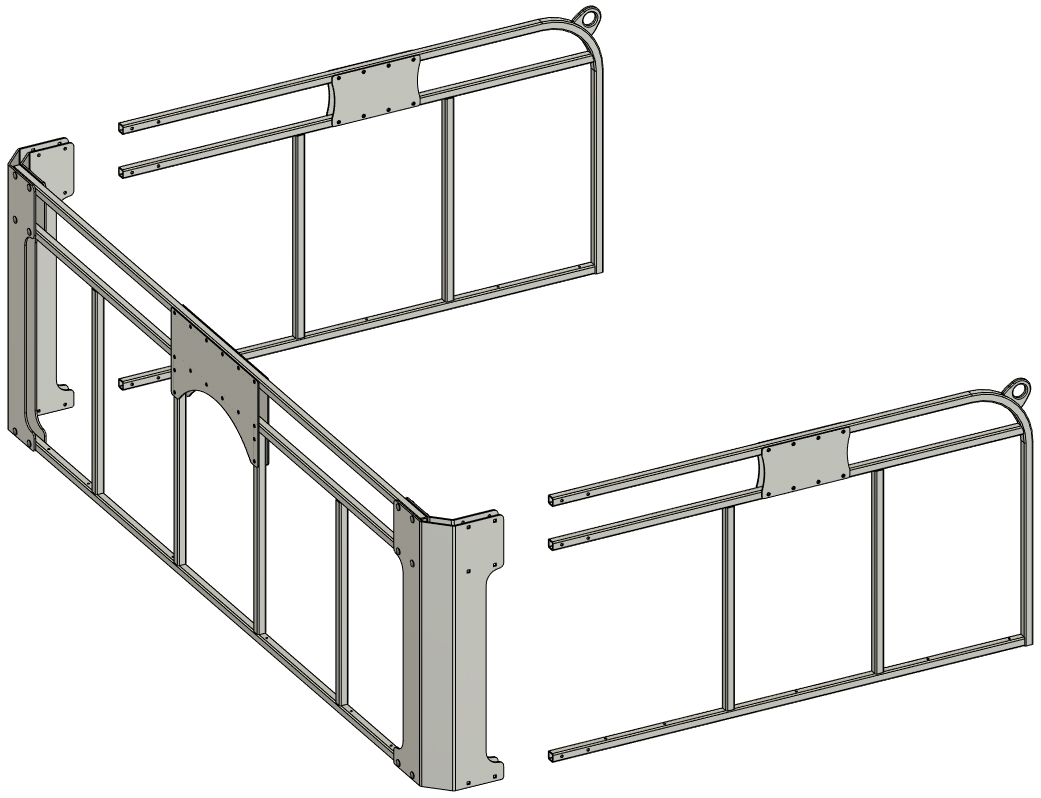
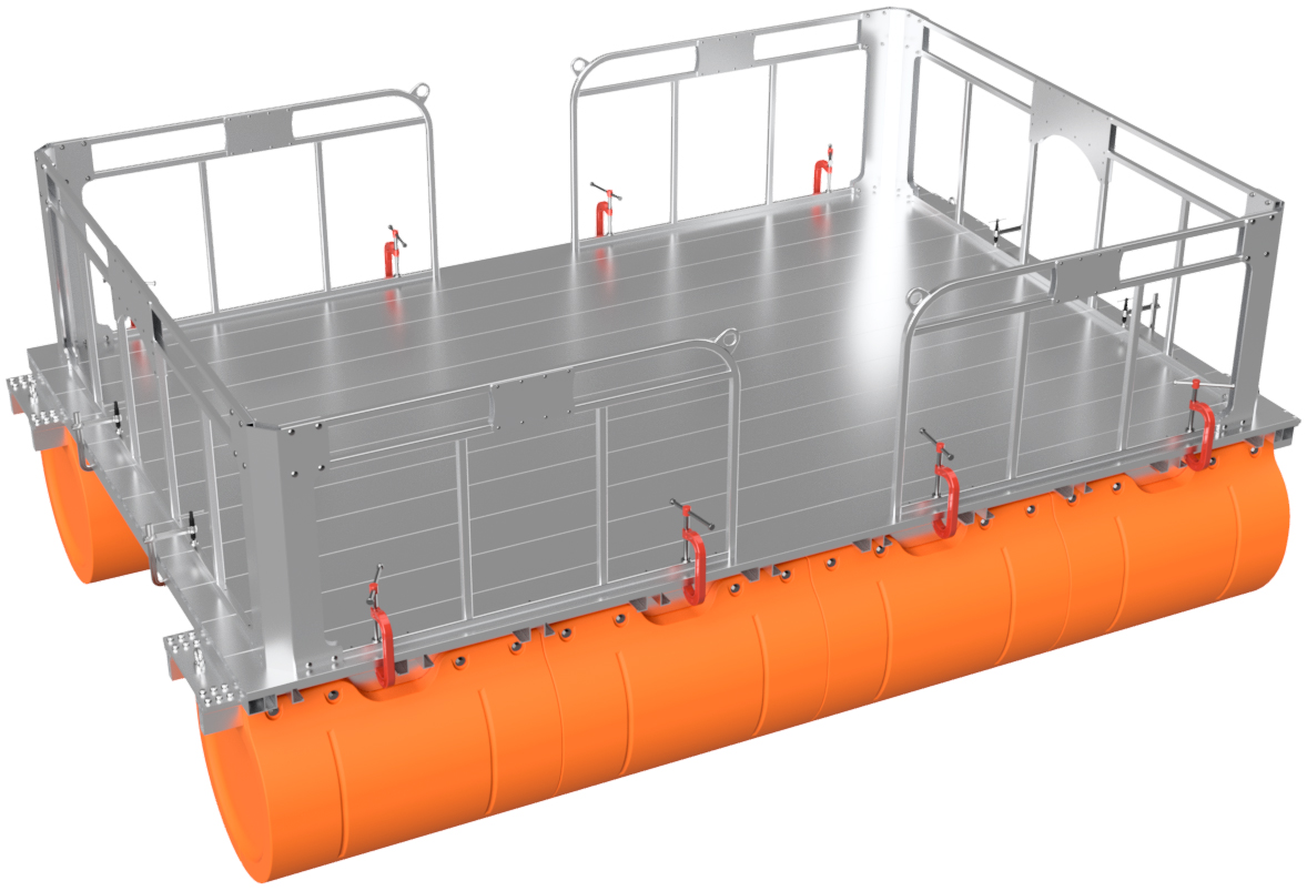
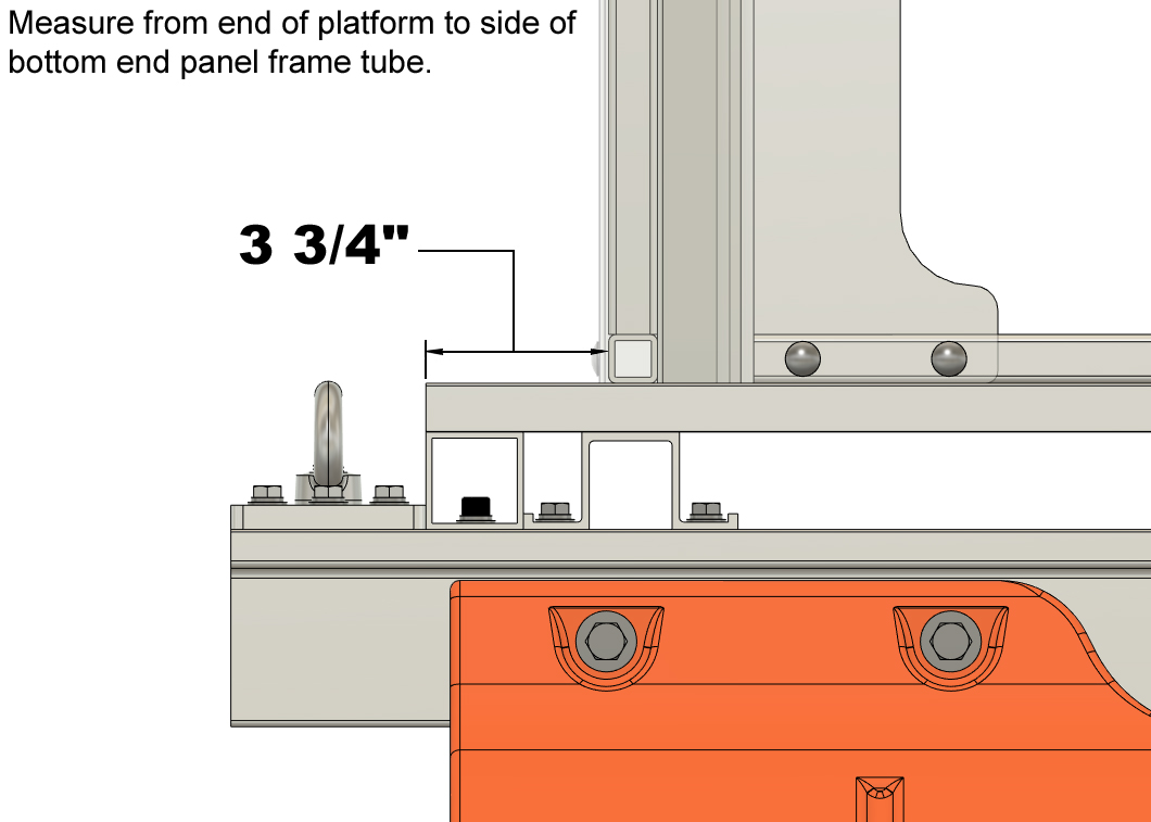
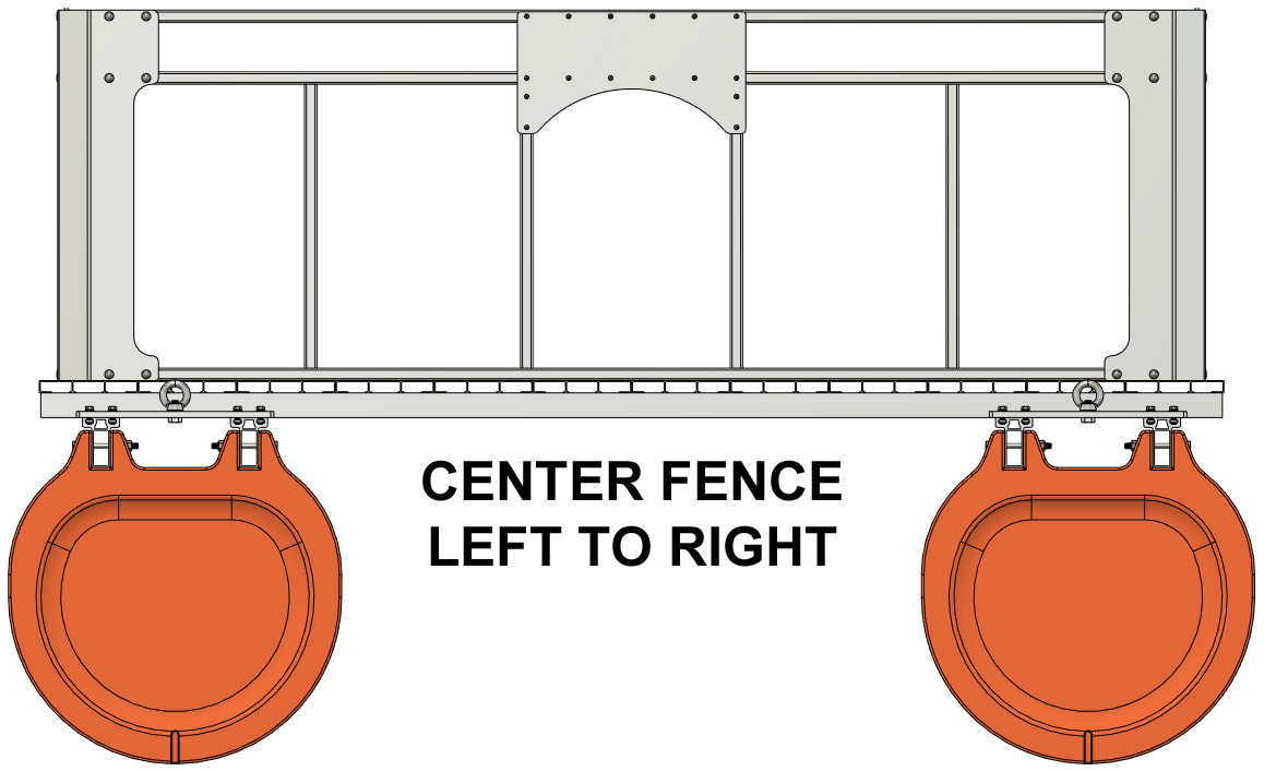
STEP 5
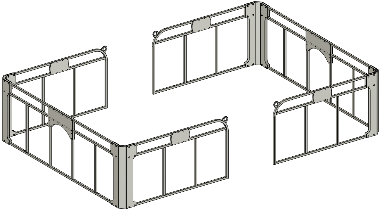
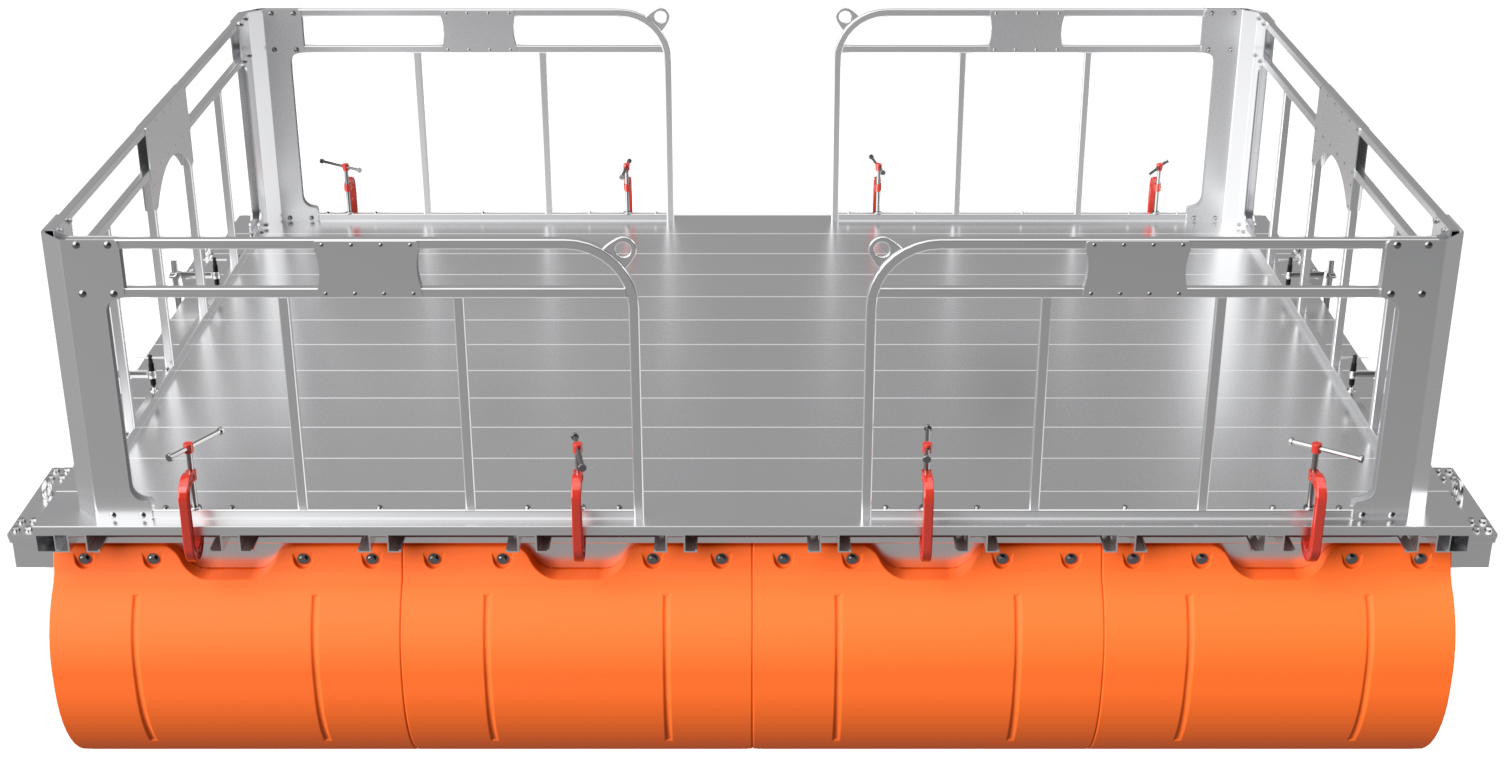
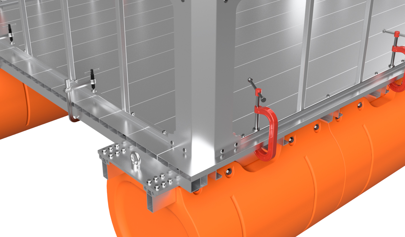
You now have two U-shaped fence assemblies on top of your work platform. From this point forward, we will be referring to each U-shaped assembly simply as "fence assembly".
Position each fence assembly so it is centered left-to-right on the platform and so that the outer edge of the bottom tube of the end panel is 3 3/4" from the end of the platform itself. BE SURE TO MEASURE TO THE SIDE OF THE TUBE AND NOT TO THE CORNER PLATE. A diagram shows this below. The 3 3/4" measurement is crutial and ensures that most of the fence mounting holes align with your frame's crossmembers. Double-check your measurements and clamp the fence assemblies in place as shown.
|
|
|
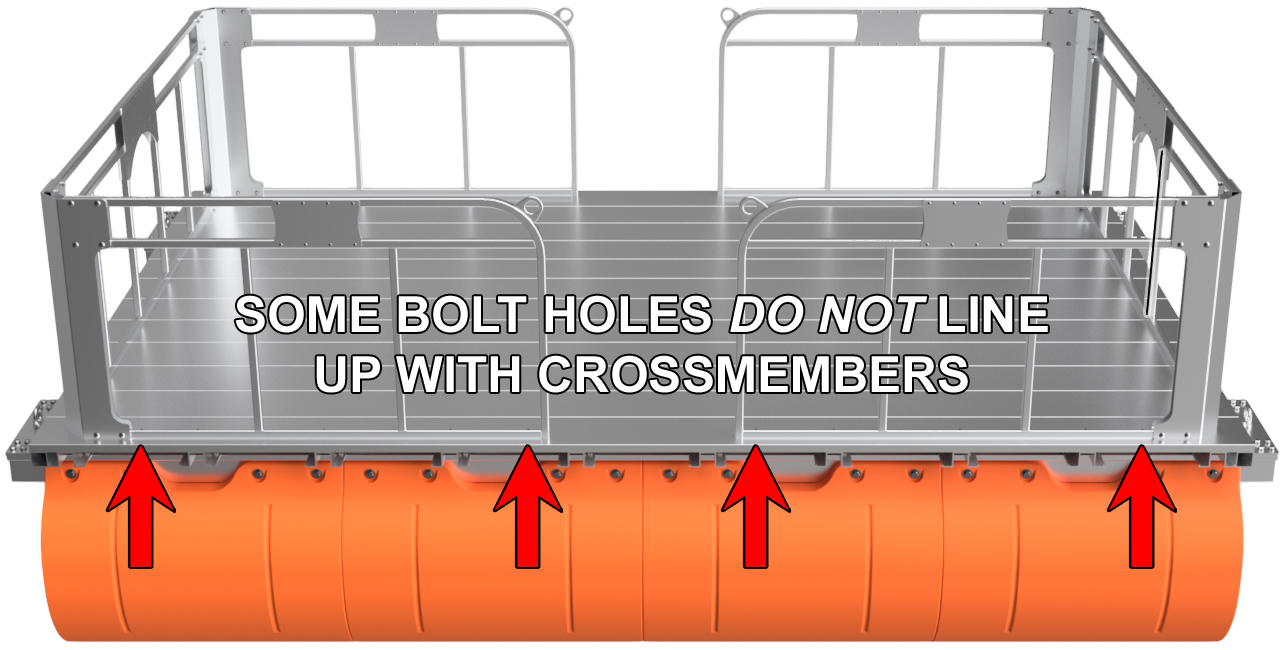
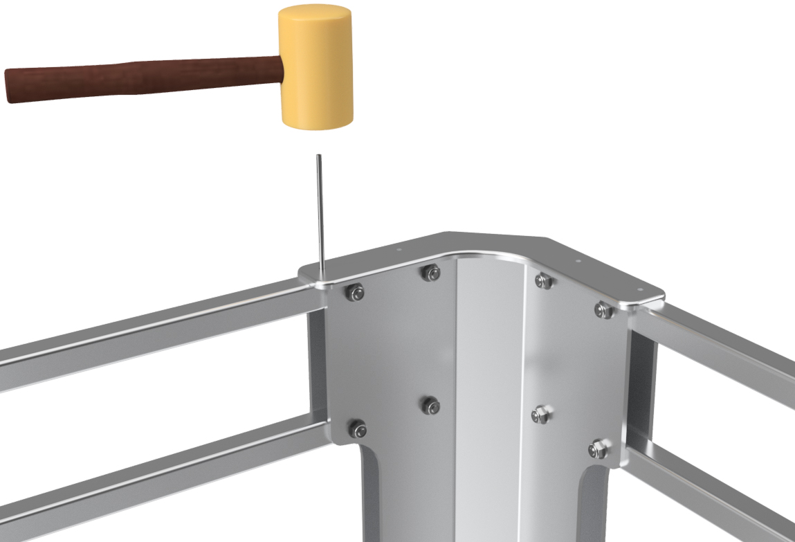
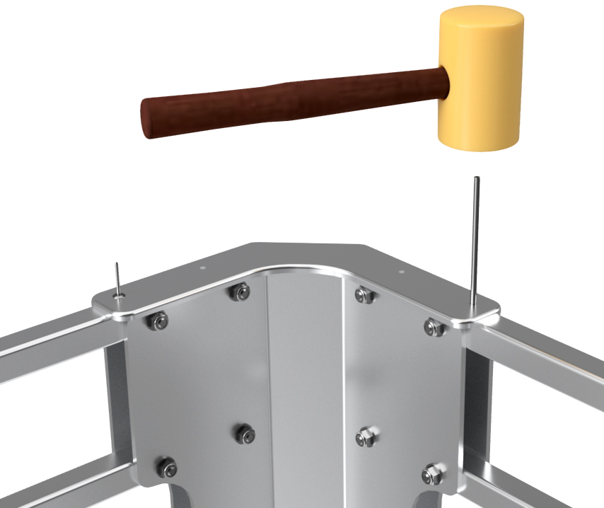
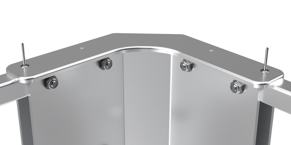
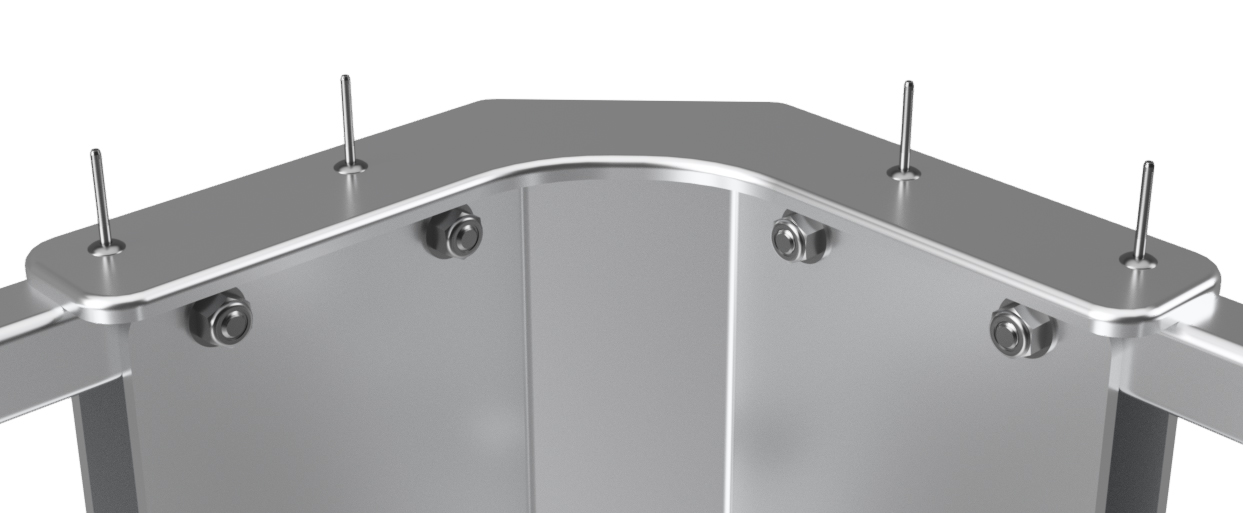
STEP 6
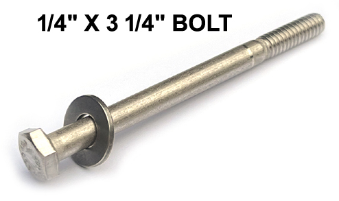
Using your drill with a 1/4" drill bit, drill through every hole in the bottom tubes of your fence assemblies (end panels and side panels) and directly through the deck of your work platform. Most of the holes will go through frame crossmembers, but a few of the side panel bolt holes will only go through the decking on your platform. After each hole is drilled, use a mallet or hammer to tap a 1/4" x 3 1/4" hex bolt with 1/4" SAE flat washer through the newly drilled hole before moving onto the next hole. This ensures that the fence doesn't move as you progress through this step.
|
|
|
|
STEP 7
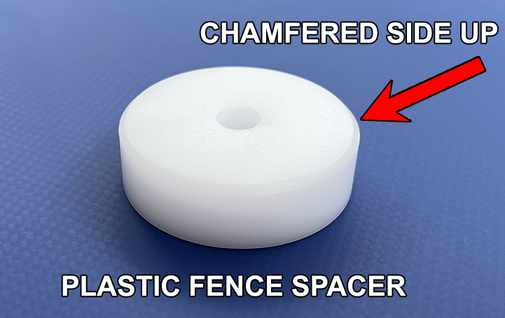
Remove all the bolts you inserted in step number 6. To do this, you may have to lift the fence assembly itself. Brush away any chips and debur any holes with rough burs (we like to use the deburring drill bit pointed out at the top of this page). Place the fence panels back in position and place the included plastic fence spacers under each fence base tube hole (between the fence and the deck of the work platform). When you do this, be sure to put the chamfer of the plastic spacer facing upward. Reinstall the 1/4" x 3/4" bolts with washers and be sure to clean any chips off the bolt threads first. If any of the bolts are tough to tap back into position, use your 1/4" drill bit to clear possible chips and try again. Double-check that every fence base tube bolt hole has a bolt installed before moving forward.
|
|
|
STEP 8
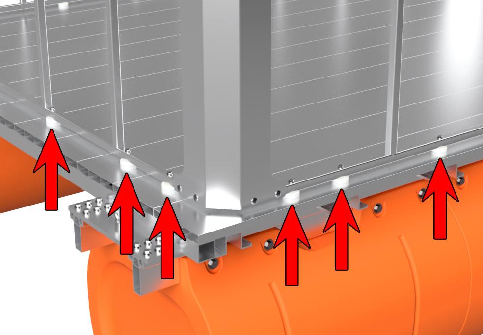
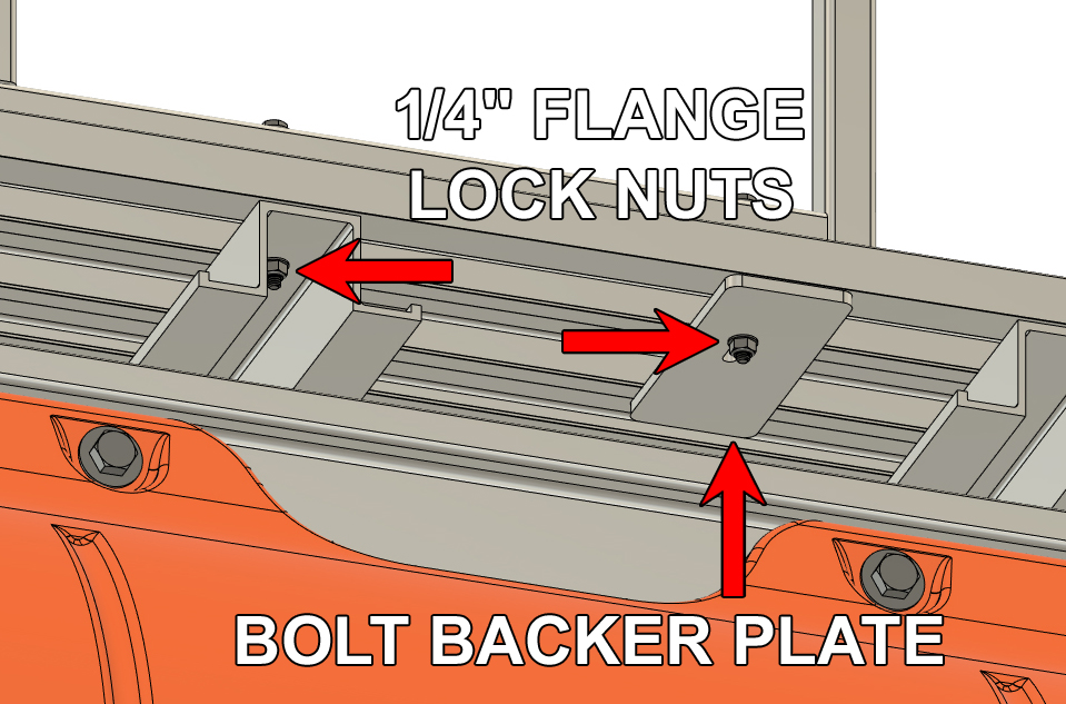
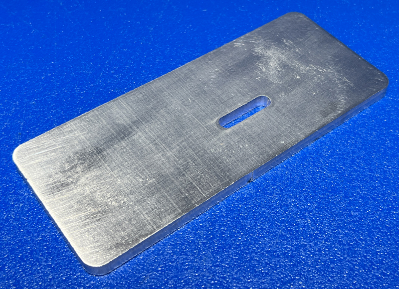
For each of the 1/4" bolts that have been installed through a frame crossmember, install a 1/4" flange lock nut and fully tighten the nut. For each bolt that only goes through the decking of your work platform, install one of the included 1/4" bolt backer plates and then a nut as shown below. These plates have an offset slot that allows it to be used in multiple positions. Orient the plate so that one end is close to the edge of the decking, but does not extent beyond it. When installed, you should not be able to see it when standing on top of the the work platform (plate does not extend from the side of the deck). We like to use a small carpenter square to make the length of the plate perpendicular to the side of the platform, but this is not completely necessary.
Double-check that every fence-to-deck nut and bolt assembly has been tightened.
|
|
|
STEP 9
We are now onto the final parts to install and this portion can be a little tricky, so take your time.
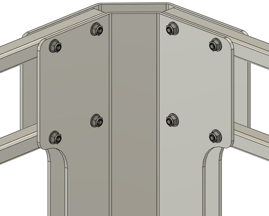
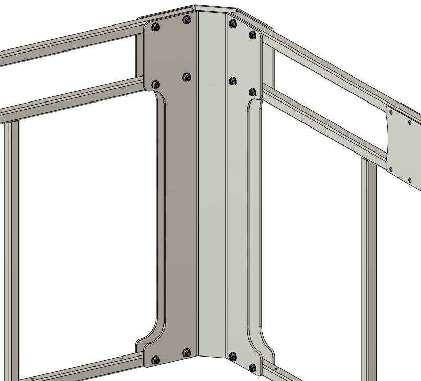
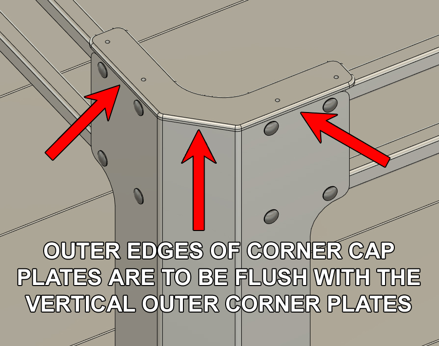
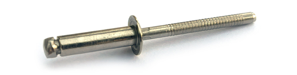
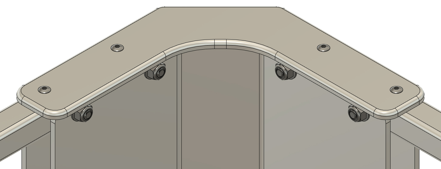
Each kit includes four 1/4" thick fence corner cap plates and rivets for installation. The cap plates have a rounded edge that faces upware. Starting at one corner of the fence assembly, place a cap plate on top of the corner plates as shown so that the outer edges of the cap plate is aligned with the outer edge of the outer corner plate. The plate will extend inwared beyond the inner corner plate. This is intentional. Hold the cap in position (will not be able to clamp it in place to hold the positiona) and use your 3/16" transer punch to mark the location of one of the outer rivet holes. Remove the cap and drill a holes the top fence tube be with your 11 gauge drill bit and debur the hole if necessary. Place the cap back into position and insert a 3/16" rivet through the cap and the newly drilled hole to hold the position (do not "pop" the rivet yet). With the rivet in place, mark the hole position (use transfer punch) at the opposite end of the cap and then debur the new hole in the upper fence tube. Insert a rivet into the new hole with the cap in place. Do not "pop" either rivet yet. Repeat the steps above for the center holes through the cap plate. Drill, debur, and insert rivets in the central holes. 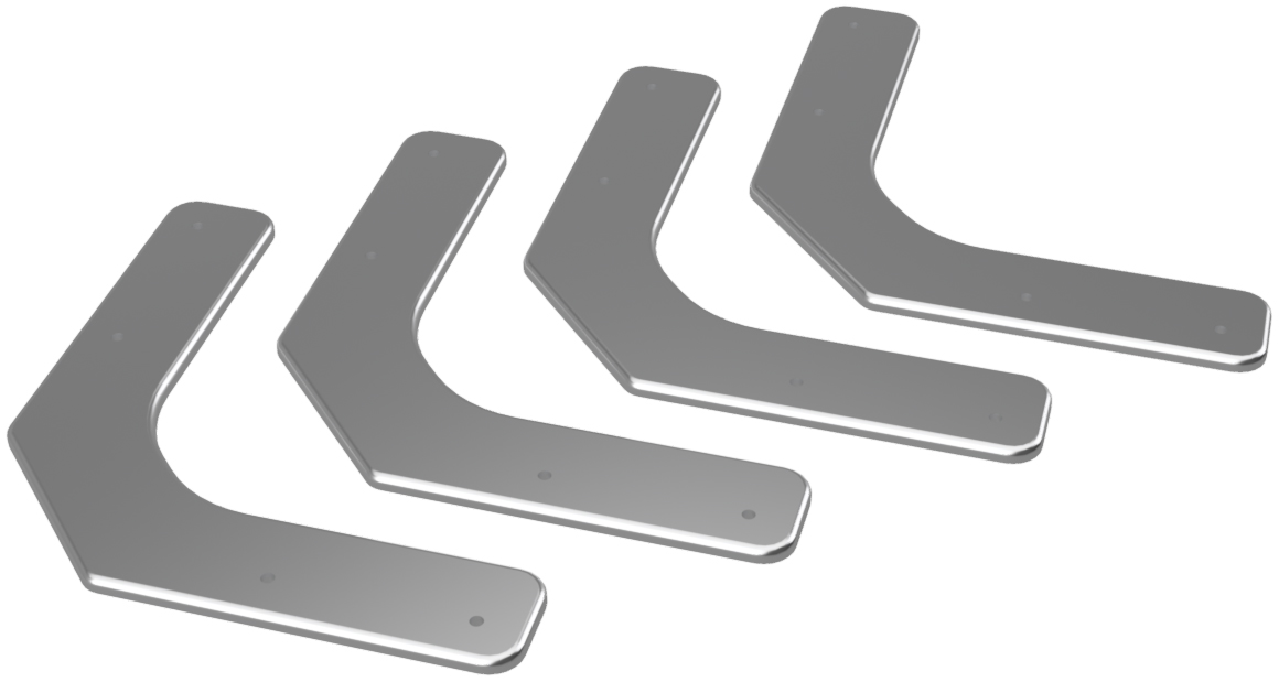 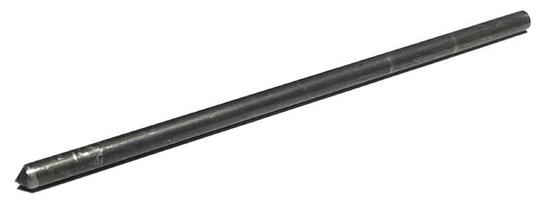
|
|
|
STEP 10
Complete the installation of the rivets with your rivet gun and "pop" the rivets into position. The cap is now installed.
Repeat step 9 and 10 for the three remaining corner caps.
|
|
|
|
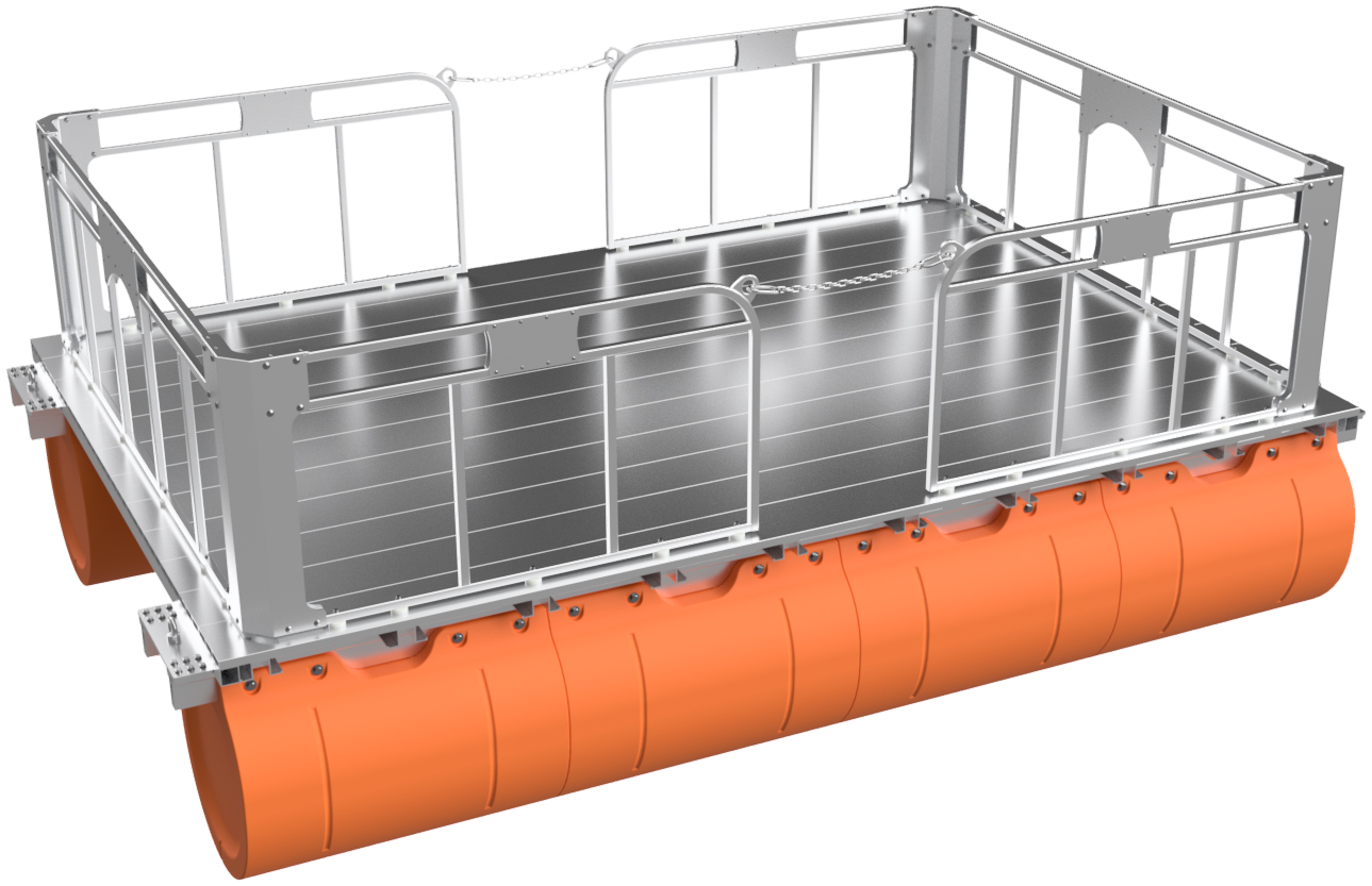
STEP 11
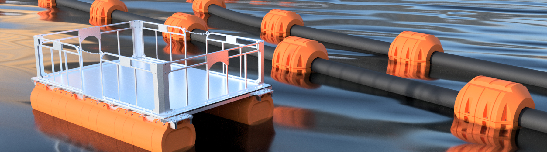
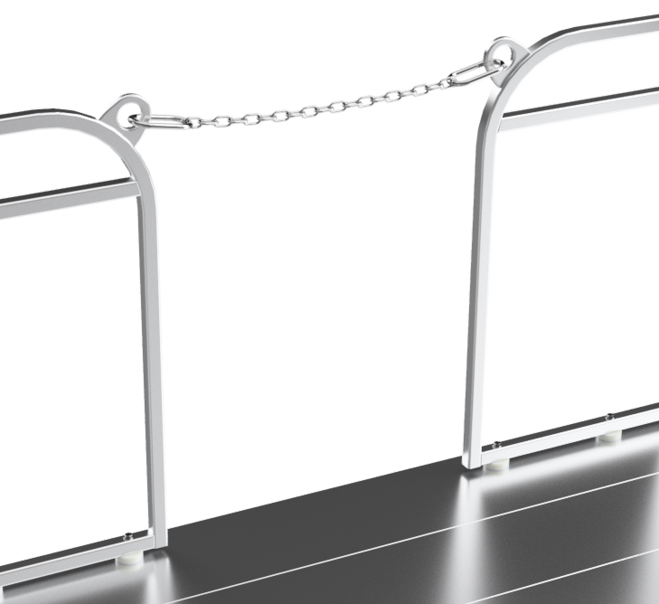
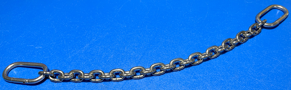
Clip a stainless steel entry chain between the side panels on either side of the work platform and your fence system installation is complete!
|
|
|
YOU'RE DONE!
|
|
|